


















Lesson 43 of 48 · Projects and Practice
Project: sizing a road culvert
A step-by-step design project that sizes a concrete culvert under a road, combining runoff estimation, full-flow capacity, velocity checks and a simple headwater estimate.
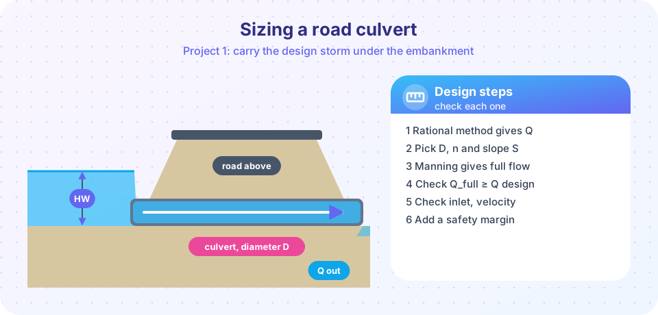
A culvert is a short tunnel that lets a stream or ditch pass under a road. Thousands of them sit under every region's roads, and each one has to carry the design storm without flooding the road or washing away the embankment. This project chains three lessons from this chapter series: hydrology (how much water?), Manning's equation (how big a pipe?) and a simplified headwater check (how high will it back up?).
What you will learn
- How to organize a design as a sequence of checkable steps.
- How to find the smallest standard pipe that carries a design flow with margin.
- How to check velocity and headwater.
- How to report a design with its assumptions.
Key terms
Culvert: a closed channel carrying water under a road, railway or embankment. Headwater (HW): the water depth upstream of the culvert inlet, measured from the inlet invert (the lowest inside point). Inlet control: the entrance limits the flow, not the pipe's friction. Full-flow capacity: the flow when the pipe runs just full, by Manning's equation. Freeboard: the vertical safety margin between the design water level and the road.
The brief
A road crosses a stream draining a 12 ha catchment with C = 0.6. The 25-year design intensity at the time of concentration is 80 mm/h. The proposed concrete pipe (n = 0.013) will be laid at a slope of 0.5% (S = 0.005). The road surface is 2.5 m above the culvert inlet invert. The design must carry the flow with a safety factor of 1.25 on capacity, keep the velocity between 0.6 and 4 m/s, and keep the headwater below 1.5 times the pipe diameter.
Step 1: design flow
Q = C i A / 360 = 0.6 × 80 × 12 / 360 = 1.60 m³/s
Step 2: full-flow capacity of candidate pipes
For a circular pipe running full, A = π D² / 4 and R = D / 4, so Manning's equation becomes
Q_full = (0.312 / n) D^(8/3) S^(1/2) (SI units)
For n = 0.013 and S = 0.005:
| D (m) | Q_full (m³/s) |
|---|---|
| 0.9 | 1.28 |
| 1.0 | 1.70 |
| 1.2 | 2.76 |
| 1.5 | 5.00 |
A 1.0 m pipe carries 1.70 m³/s, just 6% more than the design flow. With the 1.25 safety factor we need Q_full ≥ 1.25 × 1.60 = 2.00 m³/s, which rules out 1.0 m and selects D = 1.2 m.
Step 3: velocity
At full flow, v = Q_full / A. For D = 1.2 m, A = 1.131 m², so v = 2.76 / 1.131 ≈ 2.4 m/s. That is inside the 0.6 to 4 m/s limits: fast enough not to deposit sediment, slow enough not to wear the concrete. At the design flow the pipe runs partly full and the velocity is a bit lower, still well above the minimum.
Step 4: headwater estimate
Culverts often work under inlet control: the water level upstream builds up until enough head pushes the design flow through the opening. A simple conservative model treats a submerged inlet like an orifice:
Q = C_d A √(2 g (HW − D/2))
with C_d ≈ 0.6 (a typical value; manuals give tables by inlet shape). Solve for the headwater: HW = D/2 + (Q / (C_d A))² / (2g). For D = 1.2 m and Q = 1.60 m³/s:
Q / (C_d A) = 1.60 / (0.6 × 1.131) = 2.36 m/s.(2.36)² / (2 × 9.81) = 0.284 m.HW = 0.6 + 0.284 ≈ 0.88 m.
That is 0.74 of the diameter. The limit of 1.5 D is 1.8 m, and the road is 2.5 m above the invert, so the freeboard is 2.5 − 0.88 ≈ 1.6 m. The design passes. For comparison, the 1.0 m pipe would have HW ≈ 1.09 m (about 1.09 D), which also passes the headwater limit but fails the capacity margin. Note that this orifice formula is a simplification: a real design uses agency charts for the inlet type (square edge, beveled, headwall) and checks outlet control as well.
Step 5: report
A good design note lists the data, the equations, the results, the checks and the assumptions (for example the C value, the roughness, the slope). It also states what was not checked: scour at the outlet, debris blockage, fish passage and the effect of a larger future storm. A culvert that is just big enough today may be too small in 30 years if rainfall intensifies, so many agencies add a climate allowance to the design storm.
Common misconceptions
"If the pipe's full-flow capacity equals the design flow, it is correct." There is no margin for blockage, roughness changes or a larger storm.
"A steeper pipe is always better." Steep pipes raise velocity and outlet scour, which can destroy the downstream channel.
"Only the pipe matters." The inlet shape, headwater depth and outlet protection (rocks, a stilling basin) decide whether the culvert works.
Try it
First a design table and chart that pick the pipe diameter, then a headwater calculator you can change.
Press Run (or Ctrl + Enter) to see the result here.
Program input · what you'd type while the program runs
Type the answers before you press Run, one per line. Each time the program reads a line (with input()), it gets the next line from this box.
Press Run (or Ctrl + Enter) to see the console output here.
No output.
Check your understanding
Quick check · 5 questions
of 5 answered You scored / 5 · perfect!
-
1. Why choose 1.2 m instead of 1.0 m in this project?
The 1.0 m pipe carries 1.70 m³/s, below the required 2.00 m³/s. -
2. For a full circular pipe the hydraulic radius is
R = A / P = (π D²/4) / (π D) = D / 4. -
3. What does inlet control mean?
Under inlet control, the headwater needed to push water through the opening sets the capacity. -
4. A low-velocity pipe (below about 0.6 m/s) risks
Slow water cannot carry sediment. -
5. Why add a climate allowance to the design storm?
A structure built for today's storm may be undersized in the future.
Summary
- Design a culvert in steps: flow, capacity, velocity, headwater, report.
- For a full circular pipe,
Q_full = (0.312/n) D^(8/3) S^(1/2). - Apply a safety margin, then check velocity and headwater.
- State assumptions and what was not checked.
Track your progress
Create a free account to tick off lessons and pick up where you left off on any device.
of Civil Engineering Fundamentals lessons completed