


















Lesson 41 of 49 · Failure Theories and Design
Factor of safety and the design process
Define the factor of safety, apply allowable-stress and load-factor design, size a shaft with the von Mises criterion, and find which failure mode governs.
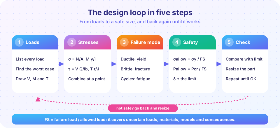
Calculations are never exact. Loads are estimated, material properties vary from batch to batch, the real part has flaws and rough surfaces that the model ignores, and the structure may be used in ways nobody foresaw. Engineers deal with this uncertainty with a deliberate margin called the factor of safety. It is the last step in a design calculation and the one that connects analysis with responsibility: too small and people get hurt, too large and the product is heavy, costly and wasteful.
What you will learn
- The definition of the factor of safety and what it covers.
- Allowable-stress design versus load-and-resistance-factor design.
- How to size a shaft from a von Mises criterion and a chosen safety factor.
- How to find the governing failure mode by checking all of them.
Key terms
- Factor of safety
FS(orn): the ratio of the failure value to the allowed or applied value. - Allowable stress
σallow = σfail / FS: the largest stress a design may have. - Load factors and resistance factors: multipliers on loads (above 1) and on strength (below 1) used by modern codes.
- Governing mode: the failure mode with the smallest margin, which decides the size.
The definition
Two equivalent ways to say the same thing:
FS = (strength of the part) / (load or stress actually applied)
σallow = σy / FS        (ductile)        σallow = σu / FS        (brittle)
A design is acceptable when the actual stress is at most σallow, that is, when the computed factor of safety is at least the required one. The factor of safety is not a measure of how much load the part can carry beyond the service load once everything else is perfect: it covers uncertainties in the loads, the material, the analysis and the consequences of failure.
Choosing a value
There is no universal number, and building and machine codes prescribe values for their fields. As rough textbook ranges only (not design values):
| Situation | Typical FS range |
|---|---|
| Well-known loads, tested material, low consequence | about 1.25 to 1.5 |
| Ordinary conditions, average materials and workmanship | about 2 to 3 |
| Uncertain loads or materials, impact, or danger to people | above 3, sometimes much larger |
Aerospace uses small safety factors (about 1.5 on limit loads) but compensates with strict material control, testing and inspection, since weight is expensive. A lifting hook or a cable carrying people is given a much larger one.
Allowable-stress and load-factor design
In allowable-stress design (ASD) you compute the stress from the service loads and compare with σallow. In load and resistance factor design (LRFD), used by most structural codes, loads are multiplied by factors greater than 1 and the nominal resistance by a factor φ less than 1:
φ · Rn ≥ Σ γᵢ · Qᵢ
Example. A beam must carry a dead load of 40 kN and a live load of 60 kN. A widely used North American combination is 1.2D + 1.6L = 48 + 96 = 144 kN, and the Eurocode combination 1.35G + 1.5Q = 54 + 90 = 144 kN happens to give the same result here. If the resistance factor is φ = 0.9, the nominal resistance must be at least 144/0.9 = 160 kN. The live load is multiplied by a larger factor than the dead load because it is less predictable.
Designing a shaft
A solid steel shaft (σy = 250 MPa) must carry M = 400 N·m and T = 300 N·m with a factor of safety n = 2 against yielding by von Mises. At the surface, σ = 32M/(πd³) and τ = 16T/(πd³), so
σe = √(σ² + 3τ²) = (16 / (π d³)) · √(4M² + 3T²)
Setting σe = σy / n:
d³ = 16 n √(4M² + 3T²) / (π σy)
   = 16 × 2 × √(4 × (4×10⁵)² + 3 × (3×10⁵)²) / (π × 250)
   = 38.9 × 10³ mm³      →   d = 33.9 mm
Round up to a standard size, say 35 mm or 36 mm, then recheck. With d = 40 mm, as in the combined-loading lesson, the factor of safety was 3.29. Doing the design backward from a chosen n gives the size directly, but remember to check other modes too: deflection and critical speeds can control a shaft, and fatigue often does.
The weakest mode wins
A part has many ways to fail, and the real factor of safety is the smallest one. A slender steel strut (round, d = 20 mm, L = 0.8 m, pinned both ends) loaded in compression by P = 12 kN has
- yielding:
n = σy·A/P = 250 × 314.2 / 12 000 = 6.5; - buckling:
Pcr = π²EI/L² = 24.2 kN,n = 24.2/12 = 2.0.
Yielding looks comfortable, but buckling governs. If you only did the stress check you would believe the margin is more than 3 times larger than it is.
Common misconceptions
- "A larger factor of safety is always better." A bigger FS costs weight, money and sometimes performance, and it can hide a poor analysis. Aim for the right margin with a good model, not for a large number.
- "FS = 2 means it can carry twice the load." Only if the load is the only uncertainty and the failure load is exactly what you assumed. The factor covers unknowns.
- "One check is enough." Check strength, stiffness, stability and fatigue, and take the smallest margin.
- "Following the code removes responsibility." Codes set minimum rules for typical cases; engineers remain responsible for situations the code did not foresee.
Try it
This TryIt sizes the shaft for different required factors of safety, using both criteria, and shows how the diameter grows slowly with n (as the cube root).
Press Run (or Ctrl + Enter) to see the result here.
Program input · what you'd type while the program runs
Type the answers before you press Run, one per line. Each time the program reads a line (with input()), it gets the next line from this box.
The second TryIt finds the governing failure mode of the strut: it computes the margin for yielding and buckling and for a range of lengths, and plots both.
Press Run (or Ctrl + Enter) to see the result here.
Program input · what you'd type while the program runs
Type the answers before you press Run, one per line. Each time the program reads a line (with input()), it gets the next line from this box.
The crossover length is where the Euler formula and the yield limit give the same load, which is why the slenderness idea of the last chapter matters for design.
Check your understanding
Quick check · 5 questions
of 5 answered You scored / 5 · perfect!
-
1. A steel has σy = 300 MPa. Which allowable stress corresponds to FS = 2.5?
σallow = σy / FS = 300 / 2.5 = 120 MPa. -
2. A part has a yielding factor of 4.0, a buckling factor of 1.8 and a fatigue factor of 2.5. What is the factor of safety of the part?
The weakest mode governs, so the safety factor is the smallest, 1.8. -
3. With the LRFD combination 1.2D + 1.6L, dead load 30 kN and live load 50 kN, what is the factored load?
1.2 × 30 + 1.6 × 50 = 36 + 80 = 116 kN. -
4. A design needs more safety margin when...
Uncertainty and severe consequences call for larger factors of safety. -
5. In the shaft-sizing formula d³ = 16 n √(4M² + 3T²)/(πσy), doubling the required n multiplies d by...
d is proportional to the cube root of n, and 2^(1/3) = 1.26.
Summary
- The factor of safety
FS = strength / applied valuecovers uncertainty in loads, material, analysis and consequences;σallow = σy/FSfor ductile materials. - Codes use allowable-stress design or load-and-resistance-factor design (
φRn ≥ Σγᵢ Qᵢ). - Sizing from a criterion: for a shaft in bending and torsion,
d³ = 16 n √(4M² + 3T²)/(π σy)with von Mises. - Check every failure mode (yield, fatigue, buckling, deflection); the smallest margin governs.
Next: Chapter 8 review
Track your progress
Create a free account to tick off lessons and pick up where you left off on any device.
of Strength of Materials lessons completed