


















Lesson 24 of 49 · Bending of Beams
Shear force and bending moment diagrams
Learn the method of sections, sign conventions and the shortcut relations between load, shear and moment to draw V and M diagrams for beams.
A beam can fail at one particular spot while the rest of it is perfectly comfortable. To find that spot, you need to know the internal shear force V and bending moment M at every position x. Plotting them gives the shear force diagram (SFD) and the bending moment diagram (BMD). Engineers read these two pictures the way doctors read an X-ray: the peaks show where to look.
What you will learn
- How to cut a beam and find
VandMwith equilibrium (the method of sections). - The sign convention used in this course.
- The three shortcuts that connect load, shear and moment.
- How to draw both diagrams for point loads and uniform loads.
Key terms
- Shear force
V: the internal force along the cut face, perpendicular to the beam axis. - Bending moment
M: the internal moment at the cut face that resists bending. - Method of sections: cutting the beam and applying equilibrium to one piece.
- Distributed load
w: a load spread along the length, in N/m or kN/m.
The method of sections
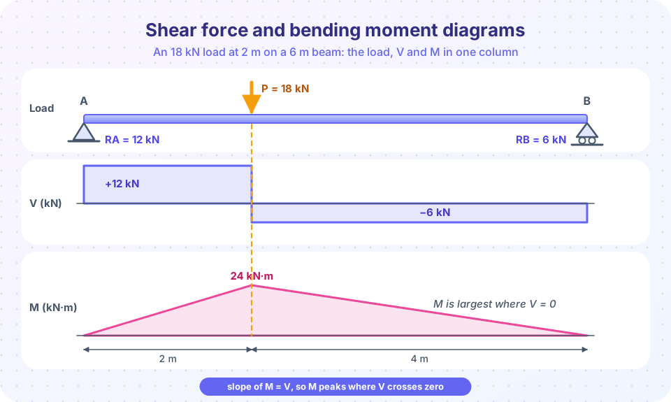
Take the beam in the figure: length 6 m, an 18 kN load at a = 2 m from the left support A.
Step 1, reactions. Moments about A give RB·6 = 18·2, so RB = 6 kN. Vertical equilibrium gives RA = 18 − 6 = 12 kN.
Step 2, cut and balance. Cut the beam at x and keep the left piece. For 0 < x < 2 m only RA acts on it, so the cut face must supply a downward force of 12 kN to balance it. In our sign convention that is V = +12 kN. Taking moments about the cut gives M = 12x, rising from 0 to 24 kN·m at x = 2 m.
For 2 m < x < 6 m the 18 kN load is also on the left piece, so V = 12 − 18 = −6 kN and M = 12x − 18(x − 2) = 36 − 6x. At x = 6 m this gives M = 0, as it must at a simple support.
Always check the end values: at a pin or roller support the moment is zero, and the shear just inside the end equals the reaction.
Sign convention
We use the common convention for the left side of a cut: a positive shear pushes the left piece up (and the right piece down), a positive moment makes the beam sag, bending it into a smile. With this choice, a simply supported beam under downward load has a positive moment everywhere.
Three shortcuts that save hours
Consider a small slice of beam of length dx under a distributed load w(x) acting downward. Equilibrium of the slice gives two differential relations:
dV/dx = −w        (slope of the shear diagram = −load intensity)
dM/dx = V         (slope of the moment diagram = shear force)
Integrating gives the area form, which is what you use in practice:
V2 − V1 = −(area under the load between 1 and 2)
M2 − M1 = +(area under the shear diagram between 1 and 2)
From these you can read the shapes without any cutting:
| If the load is... | then V is... | and M is... |
|---|---|---|
| zero | constant (flat) | a straight sloping line |
| a point load | a vertical jump equal to the load | a kink (change of slope) |
uniform w |
a straight sloping line | a parabola |
| a pure couple | unchanged | a jump equal to the couple |
Check against the figure: between the supports and the load the shear is flat, so the moment is a straight line whose slope equals V: +12 kN (a rise of 12 kN·m per meter) on the left and −6 kN on the right. Also, M has its maximum where V = 0 or changes sign, because the slope of M is V.
A uniform load
A 6 m simply supported beam carries w = 10 kN/m. The total load is 60 kN, so RA = RB = 30 kN. Then V(x) = 30 − 10x (a line from +30 to −30) and M(x) = 30x − 5x² (a parabola). V = 0 at x = 3 m, where M = 30·3 − 5·9 = 45 kN·m. This is the famous wL²/8 = 10·36/8 = 45 kN·m, and you will meet it again and again.
A cantilever
A cantilever of length L with a tip load P has V = +P all the way along and M = −P(L − x), largest at the wall: Mmax = PL (hogging, so negative in our convention). The wall is where cantilevers break.
Common misconceptions
- "The maximum moment is always at midspan." Only for symmetric loading. In our example the peak sits under the load, 2 m from the support.
- "Shear and moment are zero at the same place." No. The moment is largest where the shear is zero, but both are generally nonzero elsewhere.
- "A point load makes a jump in the moment diagram." A point load makes a jump in
Vand only a kink inM. Only an applied couple makes a jump inM.
Try it
The first example computes both diagrams numerically for any combination of point loads and a uniform load on a simply supported beam. Edit loads and w and watch the plots change.
Press Run (or Ctrl + Enter) to see the result here.
Program input · what you'd type while the program runs
Type the answers before you press Run, one per line. Each time the program reads a line (with input()), it gets the next line from this box.
The second example is an interactive widget. Slide the load along the beam and watch the reactions and the peak moment, Mmax = P·a·b/L, change.
Notice that the peak moment is largest when the load is at midspan (a = 3 m, Mmax = 27 kN·m). A load close to a support is much kinder to the beam.
Check your understanding
Quick check · 5 questions
of 5 answered You scored / 5 · perfect!
-
1. A simply supported 8 m beam carries a uniform load of 5 kN/m. What is the maximum bending moment (wL²/8)?
Mmax = wL²/8 = 5 × 64 / 8 = 40 kN·m, at midspan where the shear is zero. -
2. What does the slope of the bending moment diagram at a point equal?
From equilibrium of a small slice, dM/dx = V. -
3. Under a downward point load, the shear diagram...
A concentrated force produces a step in V equal to the size of the force; the moment diagram only gets a kink. -
4. A 4 m simply supported beam has a 20 kN load at midspan. Find the maximum moment (PL/4).
Mmax = PL/4 = 20 × 4 / 4 = 20 kN·m. -
5. Where is the bending moment zero for a simply supported beam with only downward loads?
A pin or roller cannot resist a moment, so M = 0 at the end supports.
Summary
- Find the reactions first, then cut the beam and apply equilibrium to one piece to get
V(x)andM(x). dV/dx = −wanddM/dx = V; areas under the load and shear diagrams give the changes inVandM.- A point load makes a step in
Vand a kink inM; a uniform load makes a slopingVand a parabolicM. - The maximum moment occurs where
V = 0or changes sign; for a uniform load on a simple span,Mmax = wL²/8.
Next: The flexure formula
Track your progress
Create a free account to tick off lessons and pick up where you left off on any device.
of Strength of Materials lessons completed