


















Lesson 23 of 49 · Bending of Beams
Chapter 5 overview: bending of beams
See the big picture of beam bending: loads, shear force, bending moment and stress, and what each lesson in this chapter teaches you.
Floors, bridges, aircraft wings, bicycle frames and the diving board at the pool all do the same job: they carry loads sideways across a gap. We call any long, slender member that does this a beam. Bending is the most common way that real structures fail, and it is also the topic where a little theory goes a very long way. By the end of this chapter you will be able to take a loaded beam and say how strong it is, where it is weakest, and what to change if it is not strong enough.
What you will learn
- Why a beam bends, and which fibers are stretched and which are squeezed.
- How to find the internal shear force and bending moment at any point.
- How to turn a bending moment into a stress, and a stress into a safe size.
- How the shape of a cross-section, not only its area, controls strength.
The big idea in four steps
Every beam problem in this chapter follows the same chain of thought.
- Find the reactions. Draw a free-body diagram of the whole beam and use equilibrium (
ΣF = 0,ΣM = 0), exactly as in statics. - Find the internal forces. Cut the beam at a position
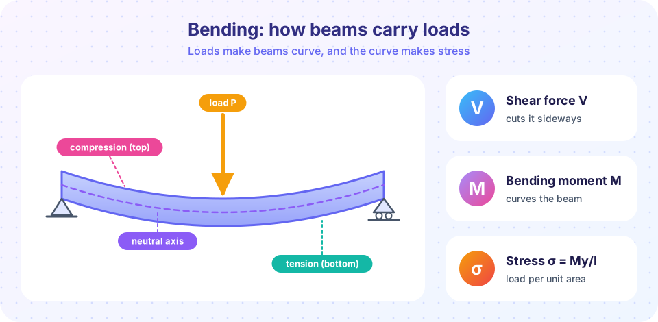
x. The piece on one side must be in equilibrium, so the cut face carries a shear forceVand a bending momentM. - Find the stress. The moment squeezes the top and stretches the bottom, with the stress growing linearly away from the middle:
σ = M·y / I. - Compare with the limit. If the largest stress is below the allowable stress, the beam is safe.
Why beams bend
Inside the beam
From moment to stress
Shape matters
Try it
Drag the slider to load a 4 m steel beam (a 100 × 200 mm rectangle, standing on its short side). The picture exaggerates the sag so you can see it. The numbers are real: δ = PL³/(48EI) and σmax = Mc/I with M = PL/4.
What each lesson covers
| Lesson | Question it answers |
|---|---|
| Shear force and bending moment diagrams | What are V and M at every point of the beam? |
| The flexure formula | How large is the bending stress, and where is it largest? |
| Second moment of area | How do I find I for a real shape, including built-up sections? |
| Chapter 5 review | Can I put the whole chain together? |
Keep your statics tools sharp: free-body diagrams and equilibrium equations are used in every lesson. If they feel rusty, the engineering statics track covers them in depth.
Check your understanding
Quick check · 3 questions
of 3 answered You scored / 3 · perfect!
-
1. A simply supported beam sags under a downward load. Which fibers are in tension?
The beam curves like a smile. The bottom becomes longer (tension) and the top becomes shorter (compression). -
2. What is the bending stress at the neutral axis in elastic bending?
Stress grows linearly with the distance y from the neutral axis, so at y = 0 it is zero. -
3. In the 4 m beam from the TryIt, doubling the load P does what to the midspan deflection?
The deflection formula δ = PL³/(48EI) is linear in P, so twice the load gives twice the deflection.
Summary
- A beam carries lateral loads by bending; the internal effects are a shear force
Vand a bending momentM. - Bending squeezes one side of the beam and stretches the other, with a neutral axis between them.
- The analysis chain is reactions, then
VandM, then stress, then comparison with an allowable value. - The shape of the cross-section enters through the second moment of area
I.
Track your progress
Create a free account to tick off lessons and pick up where you left off on any device.
of Strength of Materials lessons completed