


















Lesson 34 of 49 · Deflection and Buckling
The elastic curve and the integration method
Derive EI v'' = M(x) and integrate it with boundary conditions to find slope and deflection of cantilevers and simply supported beams, with numbers.
When a beam bends, its axis becomes a curve called the elastic curve. We write its vertical position as v(x) and its slope as θ(x) = dv/dx. The key fact connecting load to shape is the curvature relation you met in the flexure formula: 1/ρ = M/(EI). For the small slopes found in real structures, the curvature is just the second derivative d²v/dx², so the whole subject reduces to one differential equation.
What you will learn
- How
EI·v″ = M(x)follows from curvature and why it needs two integrations. - How boundary and continuity conditions fix the two constants.
- How to work through a cantilever and a simply supported beam.
- How to find where the maximum deflection occurs.
Key terms
- Elastic curve: the deflected shape of the beam's neutral axis.
- Slope
θ:dv/dx, in radians, small enough thattan θ ≈ θ. - Flexural rigidity
EI: the product of Young's modulus and the section's second moment of area. - Boundary conditions: known values of
vorθat the supports, used to find the integration constants.
The governing equation
For a beam with x along the axis and v upward, with a positive moment meaning sagging, curvature is v″ ≈ M/(EI). So:
EI · v″ = M(x)
EI · v′ = ∫ M dx + C₁          (slope)
EI · v  = ∫∫ M dx dx + C₁x + C₂   (deflection)
We assume a linear elastic material, small slopes (|θ| ≪ 1) and a section whose EI is constant, or at least known as a function of x. Shear deformation is neglected, which is accurate for slender beams.
Two constants appear, so you need two conditions. Typical ones are:
| Support | Known |
|---|---|
| Fixed (wall) | v = 0 and θ = 0 |
| Pin or roller | v = 0 |
| Symmetry at midspan | θ = 0 |
| Free end | M = 0 and V = 0 (no condition on v) |
If M(x) has several formulas along the beam (for example on each side of a point load), you integrate each segment and add matching conditions: v and θ must be continuous where the segments meet.
Example 1: a cantilever with an end load
A cantilever of length L is fixed at x = 0 and loaded by P downward at x = L. Cutting the beam at x gives M = −P(L − x) (hogging).
EI v″ = −P(L − x)
EI v′ = −P(Lx − x²/2) + C₁       v′(0) = 0   →   C₁ = 0
EI v  = −P(Lx²/2 − x³/6) + C₂    v(0)  = 0   →   C₂ = 0
At the tip, x = L:
θ(L) = −PL²/(2EI) v(L) = −PL³/(3EI)
The minus signs say the tip moves down and the slope tilts down. Numbers: a steel cantilever (E = 200 GPa) of 2 m, 100 × 200 mm section (I = 66.7 × 10⁶ mm⁴), P = 5 kN:
δ = 5000 × 2000³ / (3 × 200 000 × 66.7×10⁶) = 1.0 mm
θ = 5000 × 2000² / (2 × 200 000 × 66.7×10⁶) = 0.00075 rad = 0.043°
Example 2: a simply supported beam with a center load
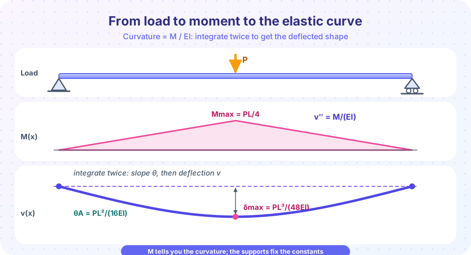
By symmetry, work on the left half, 0 ≤ x ≤ L/2, where M = P·x/2. The reaction is P/2.
EI v″ = P x / 2
EI v′ = P x²/4 + C₁       θ(L/2) = 0 by symmetry → C₁ = −P L²/16
EI v  = P x³/12 − P L² x/16 + C₂       v(0) = 0 → C₂ = 0
At x = L/2: EI·v = P L³/96 − P L³/32 = −P L³/48, so δmax = P L³/(48 EI). The slope at the support x = 0 is θ = −P L²/(16 EI). These two results are the ones in the standard tables.
Check the sign and size of your answer against intuition: a sagging beam should deflect downward, the maximum should be at midspan for symmetric loading, and the answer should scale with 1/(EI).
Where is the maximum deflection?
The maximum deflection is where the slope is zero, θ = 0. For an unsymmetrical load the maximum is not at midspan: set v′(x) = 0, solve for x, and substitute into v(x). For a point load on a simple beam, the location lies between the load and midspan, but the midspan deflection is within a few percent of the true maximum, which is why engineers often just report midspan.
Common misconceptions
- "Deflection is proportional to the moment at that point." It depends on the moment along the whole beam: deflection is the double integral. A point of zero moment can still have a large deflection.
- "Forget the constants, the integral is enough." Without
C₁andC₂you have the wrong curve. Always apply the support conditions. - "The slope formula holds for large rotations."
v″ ≈ 1/ρneeds small slopes; the exact curvature formula isv″/(1 + v′²)^(3/2). - "E and I can be mixed in any units." Keep N and mm (or N and m) throughout:
EIin N·mm² or N·m².
Try it
The first TryIt uses sympy to carry out the integration symbolically for both examples, so you can see the constants being fixed.
Press Run (or Ctrl + Enter) to see the result here.
Program input · what you'd type while the program runs
Type the answers before you press Run, one per line. Each time the program reads a line (with input()), it gets the next line from this box.
The second TryIt integrates numerically for a uniform load on a simply supported beam and compares the result with the table value 5wL⁴/(384EI).
Press Run (or Ctrl + Enter) to see the result here.
Program input · what you'd type while the program runs
Type the answers before you press Run, one per line. Each time the program reads a line (with input()), it gets the next line from this box.
Check your understanding
Quick check · 5 questions
of 5 answered You scored / 5 · perfect!
-
1. Which pair of conditions fixes the integration constants for a cantilever fixed at x = 0?
A fixed support prevents both translation and rotation. -
2. A steel cantilever has L = 2 m, I = 66.7 × 10⁶ mm⁴, E = 200 GPa and P = 10 kN. What is the tip deflection?
δ = PL³/(3EI) = 10 000 × 8 × 10⁹ / (3 × 200 000 × 66.7 × 10⁶) = 2.0 mm, twice the 5 kN result. -
3. In EI v″ = M(x), what happens when the same beam is made of aluminum (E about one third of steel)?
Deflection scales with 1/E, so a material with one third of the stiffness deflects about three times more. -
4. Where is the deflection a maximum?
A maximum of v occurs where dv/dx = θ = 0. -
5. For the simply supported beam with a center load, what is the slope at the supports (magnitude)?
From the integration: θ(0) = −PL²/(16EI). PL³/(48EI) is the deflection, not a slope.
Summary
- Small slopes give
1/ρ ≈ v″, soEI·v″ = M(x). - Integrate twice, and use the support conditions (fixed:
v = θ = 0; pin:v = 0; symmetry:θ = 0) to find the constants. - Cantilever with an end load:
δ = PL³/(3EI),θ = PL²/(2EI). Simple beam with a center load:δ = PL³/(48EI),θ = PL²/(16EI). - The maximum deflection is where the slope is zero; deflection scales with
1/(EI).
Track your progress
Create a free account to tick off lessons and pick up where you left off on any device.
of Strength of Materials lessons completed