


















Lesson 25 of 49 · Bending of Beams
The flexure formula: stress in a bent beam
Derive and use the flexure formula σ = My/I. Find where bending stress is largest, use the section modulus and size a beam for an allowable stress.
Once you know the bending moment at a section, the next question is practical: how hard is the material being pushed there? The answer is the flexure formula, one of the most useful equations in all of engineering mechanics. It was refined over centuries, starting with Galileo's early (and slightly wrong) ideas about beams, and reached its modern form through the work of Bernoulli, Euler, Navier and Coulomb. It explains why a plank is stiffer standing on its edge than lying flat, and why steel beams are shaped like the letter I.
What you will learn
- Where the formula
σ = M·y / Icomes from and what each symbol means. - Why the neutral axis passes through the centroid.
- How to compute the maximum stress and use the section modulus
S = I / c. - How to size a beam for an allowable stress, and why depth beats width.
Key terms
- Neutral axis: the line in the section where the bending stress (and strain) is zero.
- Second moment of area
I: a shape property that measures resistance to bending (units mm⁴ or m⁴). - Section modulus
S = I/c: strength-in-bending of a shape (units mm³ or m³). - Allowable stress
σallow: the largest stress we permit in design, equal to the strength divided by a safety factor.
Where the formula comes from
Three assumptions give a beautifully simple result. We assume (1) the beam is straight, with the same cross-section along its length; (2) plane sections stay plane, meaning a flat cross-section stays flat while the beam bends; and (3) the material is linearly elastic with the same E in tension and compression.
Because plane sections stay plane, the length of a fiber changes in proportion to its distance y from the neutral axis. If the beam bends to a radius of curvature ρ, the strain is
ε = −y / ρ
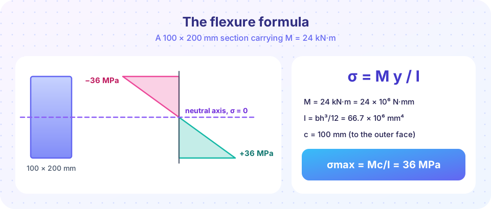
Hooke's law then gives the stress, σ = Eε = −E·y/ρ. The stress is linear in y, which is why the picture shows triangles. Two equilibrium conditions fix the rest:
- No net axial force:
∫σ dA = 0. This is only possible if the neutral axis passes through the centroid of the section. - The stresses must add up to the moment:
M = −∫σ y dA = (E/ρ)∫y² dA = E·I/ρ.
Eliminating ρ gives two classic results:
1/ρ = M / (E·I)          (curvature, used for deflections in Chapter 7)
σ = − M·y / I            (the flexure formula)
We usually drop the minus sign and decide tension or compression by looking at the beam: a positive (sagging) moment squeezes the top and stretches the bottom.
Using it: the maximum stress
The stress is biggest where |y| is biggest, at the outer fibers, a distance c from the neutral axis:
σmax = M·c / I = M / S, where S = I / c
Worked example. The beam in the previous lesson has Mmax = 24 kN·m and a rectangular section 100 mm wide and 200 mm deep (standing on its short side).
I = b·h³/12 = 100 × 200³ / 12 = 66.7 × 10⁶ mm⁴c = 100 mmσmax = (24 × 10⁶ N·mm)(100 mm) / (66.7 × 10⁶ mm⁴) = 36 MPa
The stress is tensile at the bottom face and compressive at the top. At 50 mm below the top surface the stress is M·y/I with y = 50 mm: 18 MPa in compression. Always keep units consistent: N and mm give MPa.
Orientation matters
Lay the same beam flat (200 mm wide, 100 mm deep). Now I = 200 × 100³/12 = 16.7 × 10⁶ mm⁴ and c = 50 mm, so σmax = 24 × 10⁶ × 50 / 16.7 × 10⁶ = 72 MPa. Same material, same area, twice the stress. Depth enters I as a cube, so putting material far from the neutral axis is the cheapest way to gain strength. This is also why you use a ruler on its edge and not flat when you try to bend it.
Designing for an allowable stress
Design flips the question around: given M and an allowable stress, find the section. The required section modulus is
S_required = Mmax / σallow
Suppose the allowable stress is 150 MPa (a typical value for structural steel after a safety factor). Then S_required = 24 × 10⁶ / 150 = 160 × 10³ mm³. For a rectangle S = b·h²/6; with b = 100 mm this gives h = √(6 × 160 × 10³ / 100) = 98 mm. Use the next standard size, perhaps 100 mm. The 200 mm deep beam we started with is therefore generously strong at 36 MPa. Whether it is stiff enough is a different question, answered in Chapter 7.
Why I-beams?
Material near the neutral axis carries little stress, so it is wasted. An I-beam puts most of its area in two flanges far from the axis and keeps only a thin web in the middle. For the same area, it has a much larger I than a rectangle, and so a much larger S. A hollow tube follows the same logic.
Common misconceptions
- "Stress is largest at the neutral axis." The opposite: bending stress is zero there and largest at the outer fibers. (Shear stress behaves differently; see Chapter 6.)
- "I only depends on the area." It depends on how the area is distributed. Two sections with equal area can differ in
Iby a factor of ten or more. - "The formula works above the yield point." The linear distribution assumes elastic behavior. Beyond yielding, the stress profile changes and the formula underestimates the strength of the section's reserve.
- "Use any units you like." Mixing kN·m with mm⁴ gives a number that is wrong by a factor of a thousand. Convert first.
Try it
This calculator compares four ways of making a beam from about 20,000 mm² of steel under the same 24 kN·m moment: a rectangle on edge, the same rectangle flat, a solid circle, and a hollow box.
Press Run (or Ctrl + Enter) to see the result here.
Program input · what you'd type while the program runs
Type the answers before you press Run, one per line. Each time the program reads a line (with input()), it gets the next line from this box.
The second example draws the stress profile through the depth for the two rectangles, so you can see how the flat beam climbs twice as steeply.
Press Run (or Ctrl + Enter) to see the result here.
Program input · what you'd type while the program runs
Type the answers before you press Run, one per line. Each time the program reads a line (with input()), it gets the next line from this box.
Check your understanding
Quick check · 5 questions
of 5 answered You scored / 5 · perfect!
-
1. A rectangular beam has I = 20 × 10⁶ mm⁴, c = 50 mm and carries M = 10 kN·m. What is σmax?
σ = Mc/I = (10 × 10⁶ N·mm)(50 mm) / (20 × 10⁶ mm⁴) = 25 MPa. -
2. Where does the neutral axis pass through a symmetric section under pure bending?
Zero net axial force requires that the neutral axis passes through the centroid. -
3. A beam is turned from lying flat to standing on its edge (depth doubles, width halves). What happens to S = bh²/6?
S = bh²/6 changes by (1/2)(2²) = 2, so the section is twice as strong in bending. -
4. Which assumption is NOT used in deriving σ = My/I?
The stress is not uniform. It varies linearly with y, which is the main result. -
5. The required section modulus for Mmax = 30 kN·m and σallow = 120 MPa is...
S = M/σallow = 30 × 10⁶ / 120 = 250 × 10³ mm³.
Summary
- Plane sections remaining plane makes the strain, and in elastic bending the stress, linear in
y. - The neutral axis passes through the centroid;
σ = M·y/Iand1/ρ = M/(E·I). - The maximum stress is
σmax = M·c/I = M/S, at the outer fibers; tension on the stretched side, compression on the squeezed side. - Depth is the powerful design variable; I-beams and tubes place material far from the neutral axis.
- For design, compute
S_required = Mmax/σallowand pick a shape that exceeds it.
Next: Second moment of area
Track your progress
Create a free account to tick off lessons and pick up where you left off on any device.
of Strength of Materials lessons completed