


















Lesson 23 of 47 · Steel Design
Tension members: gross yield and net rupture
Design steel tension members with LRFD: gross-section yield, net-section rupture, effective net area, slenderness and block shear, with worked numbers.
A tension member is the simplest structural element: a rod, bar, angle or plate that is pulled along its axis. Hangers, truss bottom chords, bracing and cable-like ties are all tension members. There is no buckling to worry about, so you might expect the design to be trivial. It is not, because of one detail: connections need holes or welds, and a hole turns a strong bar into a weaker cross-section at exactly the place where the load enters.
What you will learn
- The two main limit states of a tension member and why each uses a different area and stress.
- How to compute net area
Anand effective net areaAe. - What shear lag is and how the factor
Uaccounts for it. - The slenderness guideline and the idea of block shear.
Key terms
Gross area Ag: the full cross-sectional area, ignoring holes.
Net area An: gross area minus the area removed by holes.
Effective net area Ae: U × An, the net area reduced for shear lag.
Shear lag: uneven stress when a connection joins only part of the cross-section.
Block shear: tearing out a block of steel along a path of shear and tension.
Limit state 1: yielding of the gross section
Imagine the whole length of the bar stretching. If the stress over the full area Ag reaches Fy the bar elongates a lot, and the structure will deform or sag excessively. That is not a collapse, but it is unacceptable, so it is a limit state:
φPn = 0.90 × Fy × Ag
The gross area is used because yielding over the entire length matters more than local effects. Note that the force is in newtons when stress is in MPa (N/mm²) and area is in mm².
Limit state 2: rupture of the net section
At a bolt hole, only the net area carries the force, and local stress is higher because of the stress concentration. Ductile steel yields locally around the hole and redistributes, so we do not need to consider the peak stress; we only need to prevent the net section from reaching the ultimate stress Fu and tearing:
φPn = 0.75 × Fu × Ae
Here Ae = U × An. For a plate or a member connected through all its elements, U = 1.
Net area with holes
For bolted tension members, the code treats the hole as slightly bigger than the bolt, because punching or drilling damages some steel around the hole. A standard rule is to count the hole diameter as the nominal hole size plus 2 mm. A 20 mm bolt uses a 22 mm hole in a standard design, so the width deducted per hole is 24 mm:
An = (b − n × dh) × t (holes in one line across the width)
where n is the number of holes in the cross-section considered, dh = 24 mm for our example, b the plate width and t its thickness.
Worked example
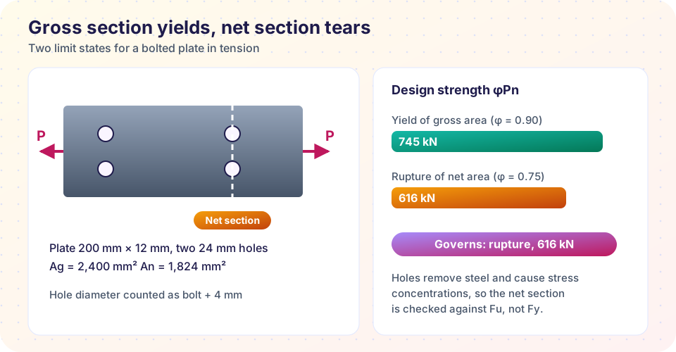
A 200 mm × 12 mm plate of Fy = 345 MPa, Fu = 450 MPa carries bolted tension, two 20 mm bolts in a line across the width.
Ag = 200 × 12 = 2,400 mm².- Yield:
φPn = 0.90 × 345 × 2,400 = 745,200 N = 745 kN. An = (200 − 2 × 24) × 12 = 1,824 mm², andU = 1, soAe = 1,824 mm².- Rupture:
φPn = 0.75 × 450 × 1,824 = 615,600 N = 616 kN. - The smaller value governs: 616 kN.
A required factored tension of Pu = 580 kN passes (ratio 0.94); Pu = 650 kN fails.
Staggered holes
If holes are staggered, a tear can zig-zag from hole to hole across the section, travelling a longer path but through less steel at each step. The path length is corrected by adding s²/(4g) for each diagonal segment, where s is the longitudinal spacing (pitch) and g the transverse spacing (gage) between holes. You check every possible failure path and use the smallest net area.
Shear lag and the factor U
When a member such as an angle is connected only through one leg, the outstanding leg is not fully engaged near the connection. The stress is not uniform, and the member is weaker than Fu × An would suggest. The code handles it with a reduction factor:
U = 1 − x̄ / L
where x̄ is the distance from the connection plane to the centroid of the member and L is the length of the connection. A longer connection means a higher U. Typical values are between 0.6 and 0.9 for angles and tees. For a plate welded or bolted across its full width, shear lag does not apply and U = 1.
To increase the efficiency of a single-angle brace, make the connection longer (more bolts in the line of force) or connect both legs.
Block shear
Another way a connection can fail is tearing out a block of steel: shear along the bolt line and tension across the end. The strength is the sum of a shear part and a tension part, each using the relevant net area, with a cap on the shear part based on yield of the gross shear area. Block shear is checked at the end of beams that are coped (cut back) and at gusset plates. You will usually do it by software or by a table, but the physical picture is useful: a block of steel pulled out of the plate.
Slenderness of tension members
A tension member has no buckling, but a long and thin one vibrates and sags under its own weight and can be damaged in handling. Codes recommend (it is a preference, not a strength requirement) a slenderness L/r of no more than 300 for members other than rods. Rods and cables are exempt.
Common misconceptions
"The weakest cross-section sets the yield strength." Yielding is checked on the gross area, because that is what controls overall elongation. The net section is checked against fracture at Fu, not at Fy.
"Holes always reduce strength by their area." The area is reduced, but ductile steel redistributes stress. That is why you can use the net area against Fu without a separate stress concentration factor.
"U can be ignored for angles." An angle bolted through one leg can lose 10 to 40 percent of its net-section strength to shear lag.
Try it
Press Run (or Ctrl + Enter) to see the result here.
Program input · what you'd type while the program runs
Type the answers before you press Run, one per line. Each time the program reads a line (with input()), it gets the next line from this box.
Check your understanding
Quick check · 5 questions
of 5 answered You scored / 5 · perfect!
-
1. Which area is used for the yield check of a tension member?
Yielding over the whole length governs elongation, so the gross area is used with Fy. -
2. For a 150 mm × 10 mm plate with one 24 mm hole, what is the net area?
(150 − 24) × 10 = 1,260 mm². -
3. What does the shear lag factor U account for?
U = 1 − x̄/L reduces the net area when connection is through only one leg or flange. -
4. A member has φPn(yield) = 700 kN and φPn(rupture) = 640 kN. Its design strength is
The smaller limit state governs. -
5. The recommended slenderness limit for tension members (other than rods) is about
It is a guide against sag and vibration, not a strength requirement.
Summary
- Check gross yield:
φPn = 0.90 Fy Ag. Check net rupture:φPn = 0.75 Fu Ae. - Net area subtracts holes (nominal hole plus 2 mm); staggered holes add
s²/4gfor each diagonal. - Shear lag reduces net area with
U = 1 − x̄/Lwhen a connection engages only part of the section. - Check block shear at connection ends; keep
L/r ≤ 300as a guide.
Next: Columns and buckling
Track your progress
Create a free account to tick off lessons and pick up where you left off on any device.
of Structural Engineering lessons completed