


















Lesson 19 of 47 · Indeterminate Structures
Moment distribution: the Hardy Cross method
Learn moment distribution: fixed-end moments, stiffness, distribution factors and carry-over, with a worked two-span beam, a step-by-step stepper and a runnable solver.
Before computers, engineers designed continuous bridges and multi-storey frames with a method that needs nothing more than arithmetic: moment distribution, published by Hardy Cross in 1930. It treats a structure as a set of beams meeting at joints. First lock every joint so nothing can rotate, then release the joints one at a time and let the locked-in moments flow to the neighbours until everything is in balance. It is still the best way to see how moments share between members according to their stiffness.
What you will learn
- The four ingredients: fixed-end moments, member stiffness, distribution factors and carry-over.
- The sign convention and the cycle of balance and carry-over.
- How to solve a two-span continuous beam by hand and in code.
- When the method needs extra care (sway frames).
Key terms
Fixed-end moment (FEM): the end moments of a member when both ends are held fixed against rotation. Stiffness (k): the moment needed to rotate one end by a unit angle: 4EI/L if the far end is fixed, 3EI/L if it is pinned. Distribution factor (DF): the share of an unbalanced joint moment taken by each member, k divided by the sum of k at the joint. Carry-over factor: the fraction (one half, for a fixed far end) of a moment applied at one end that appears at the other end.
The ingredients
1. Fixed-end moments. With both ends locked, a loaded member develops end moments. Standard values (clockwise end moment positive, A at the left, B at the right):
| Load | FEM at A | FEM at B |
|---|---|---|
| Uniform w over L | −wL²/12 | +wL²/12 |
| Point load P at midspan | −PL/8 | +PL/8 |
| Point load P at distance a from A (b = L − a) | −Pab²/L² | +Pa²b/L² |
2. Stiffness and distribution factors. If you apply a moment to a locked joint and let it rotate, each member attached to it resists in proportion to its stiffness. With the far end fixed, k = 4EI/L. The joint moment splits by
DF_member = k_member / Σ k at the joint
and the DFs at any joint add up to 1.
3. Carry-over. When a member end is rotated, the far end (if fixed) develops half the moment, with the same sign. So whenever you balance a joint, half of each distributed moment is carried to the other end of that member.
4. The cycle. Lock all joints and write the FEMs. For each free joint in turn: add up the end moments (the unbalance), distribute minus that amount by the DFs, carry half to the far ends. Repeat until the carry-overs become negligible. The final end moment of each member is the sum of its FEM, all distributed moments and all carried moments.
Worked example: two spans, one cycle
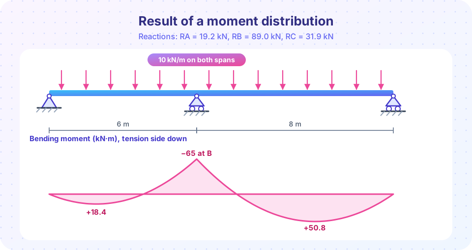
A continuous beam ABC has simple supports at A and C and a middle support at B. The spans are AB = 6 m and BC = 8 m, EI is constant, and both spans carry w = 10 kN/m.
Shortcut for a pinned far end. Instead of locking A and C and releasing them, use the modified stiffness 3EI/L for members whose far end is pinned and the modified FEM wL²/8 (a pinned-fixed member under UDL). Then only joint B needs balancing, and no carry-over is needed:
- k_BA = 3EI/6 = 0.500 EI, k_BC = 3EI/8 = 0.375 EI. DF_BA = 0.5714, DF_BC = 0.4286.
- FEM_BA = +wL²/8 = +45 kN·m, FEM_BC = −wL²/8 = −80 kN·m. Unbalance at B = 45 − 80 = −35 kN·m.
- Distribute +35 kN·m: M_BA = 45 + 0.5714 × 35 = +65.0, M_BC = −80 + 0.4286 × 35 = −65.0.
The moments at B now sum to zero. The hogging moment over the middle support is 65 kN·m, matching the figure.
Check with the three-moment equation: M_B = −w (L1³ + L2³) / (8 (L1 + L2)) = −10 (216 + 512) / (8 × 14) = −65.0 ✓.
Reactions and spans. With M_B = 65 kN·m hogging: R_A = wL1/2 − M_B/L1 = 30 − 10.83 = 19.17 kN, R_C = 40 − 65/8 = 31.88 kN, R_B = 140 − 19.17 − 31.88 = 88.96 kN. The span moments follow from M(x) = R_A x − wx²/2: maximum 18.4 kN·m at x = 1.92 m in AB, and 50.8 kN·m at 3.19 m from C in BC.
Press Run (or Ctrl + Enter) to see the result here.
Program input · what you'd type while the program runs
Type the answers before you press Run, one per line. Each time the program reads a line (with input()), it gets the next line from this box.
Joint B reads 65 kN·m at the end of every cycle here, because in this two-span beam each cycle returns B to the same balanced state; what shrinks is the moment that keeps being carried back to the simple ends and removed again, shown in the plot. In a bigger frame with many free joints every joint changes from cycle to cycle, and you stop when the unbalanced moments are smaller than the accuracy you need.
Step through the cycles yourself
Watch M_BA climb to 65 and M_BC fall to −65 as the joints are balanced in turn, and watch M_AB and M_CB settle to zero, as they must at simple ends.
Frames and sway
For a frame that cannot sway (braced, or symmetric under symmetric loading), the method works exactly as above, with columns treated as members like any other. If the frame can sway sideways, the joints translate as well as rotate, and a second set of moments from the sway must be added, solved by an additional equilibrium equation for the storey shear. The method still works but needs more bookkeeping, and nowadays this is where software is used.
Common misconceptions
"Distribution factors depend on the load." They depend only on member stiffness (EI/L) and the far-end condition. The loading affects the fixed-end moments.
"Carry-over always halves." Half is for a far end that is fixed. If the far end is a pin or roller, nothing is carried over (or use the modified stiffness 3EI/L).
"The method needs the actual EI." Only the ratios EI/L matter for distribution, so relative values are enough. Absolute EI is needed again only for deflections and settlement effects.
Check your understanding
Quick check · 5 questions
of 5 answered You scored / 5 · perfect!
-
1. A uniformly loaded fixed-fixed member of 6 m with w = 12 kN/m has a fixed-end moment of
wL²/12 = 12 × 36 / 12 = 36 kN·m. -
2. At a joint, two members have stiffnesses 4EI/6 and 4EI/8 (same EI). What is the distribution factor of the shorter member?
k1 = 0.667, k2 = 0.5, so DF1 = 0.667/1.167 = 0.5714. -
3. What is the carry-over factor for a member with a fixed far end?
A moment applied at one end of a prismatic member induces half of it at the fixed far end. -
4. After balancing, the sum of the end moments at a free joint is
A balanced joint is in rotational equilibrium: the member end moments sum to zero. -
5. When the far end of a member is pinned, a common shortcut is to use stiffness
A pinned far end makes the member more flexible; its stiffness is 3EI/L and no moment is carried over.
Summary
- Lock the joints, write the fixed-end moments, then balance each joint and carry half the distributed moments to the far ends.
- Distribution factors come from member stiffnesses (4EI/L, or 3EI/L with a pinned far end).
- The worked beam gives a hogging moment of 65 kN·m at B after one pass, verified by the three-moment equation.
- Reactions follow from end moments and equilibrium.
- Sway frames need extra equations; software usually takes over there.
Track your progress
Create a free account to tick off lessons and pick up where you left off on any device.
of Structural Engineering lessons completed