


















Lesson 15 of 47 · Analysis of Statically Determinate Structures
Beam deflection by double integration
Find beam slope and deflection by integrating the moment-curvature equation EI v″ = M, use standard formulas and superposition, and check serviceability limits with code.
A beam that is strong enough can still be unusable. If a floor sags noticeably, plaster cracks, doors jam and people lose confidence in it. Deflection is how far a beam moves under load, and checking it is a serviceability requirement in every code. This lesson derives deflections from the bending moment you found in the last lesson, collects the standard formulas and shows how a deflection limit can control the design.
What you will learn
- The moment-curvature relation EI v″ = M and where it comes from.
- How to integrate twice and fix the constants with boundary conditions.
- The standard deflection formulas and how to combine them by superposition.
- How to compare deflection with a span-to-depth limit.
Key terms
Deflection (v): vertical displacement of the beam's axis. Slope (θ = dv/dx): the rotation of the beam's axis. E: modulus of elasticity, the material's stiffness. I: second moment of area of the cross-section, the section's resistance to bending. EI: flexural rigidity. Boundary conditions: known deflections or slopes at supports that fix the integration constants.
From moment to curvature
A beam in bending curves. In the elastic range, the curvature κ (how sharply the axis bends) is proportional to the moment and inversely proportional to the stiffness:
κ = M / (EI)
For small deflections the curvature is approximately the second derivative of the deflection, so
EI · d²v/dx² = M(x)
where v is measured upward and sagging moment is positive. A sagging beam curves like a smile, so v″ is positive and the deflection v itself is negative (downward). Integrating once gives slope; integrating twice gives deflection:
EI v′ = ∫ M dx + C1          (slope)
EI v  = ∫∫ M dx dx + C1 x + C2   (deflection)
The two constants C1 and C2 come from the supports: a pin or roller means v = 0; a fixed support means v = 0 and v′ = 0.
Worked example: simply supported beam, uniform load
The moment is M(x) = wLx/2 − wx²/2. Integrate:
EI v′ = wLx²/4 − wx³/6 + C1
EI v  = wLx³/12 − wx⁴/24 + C1 x + C2
At x = 0, v = 0, so C2 = 0. At x = L, v = 0, so wL⁴/12 − wL⁴/24 + C1 L = 0, giving C1 = −wL³/24. At midspan, x = L/2:
EI v(L/2) = wL⁴/96 − wL⁴/384 − wL⁴/48 = −5wL⁴/384
so the sag is δmax = 5wL⁴/(384 EI). The end slope is θ = wL³/(24 EI).
Press Run (or Ctrl + Enter) to see the result here.
Program input · what you'd type while the program runs
Type the answers before you press Run, one per line. Each time the program reads a line (with input()), it gets the next line from this box.
Sympy reproduces the hand derivation. The negative sign just says the deflection is downward.
Standard formulas and superposition
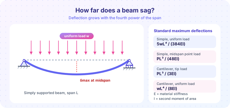
Integration for every beam is slow, so engineers use tables of standard cases (maximum deflection at the point listed):
| Beam and load | Maximum deflection |
|---|---|
| Simple, uniform load w | 5wL⁴ / (384EI) at midspan |
| Simple, point load P at midspan | PL³ / (48EI) |
| Cantilever, point load P at the tip | PL³ / (3EI) |
| Cantilever, uniform load w | wL⁴ / (8EI) |
For small deflections the beam behaves linearly, so the deflection from several loads is the sum of the deflections each would cause alone. That is the principle of superposition. A cantilever with both a uniform load and a tip load deflects at the tip by wL⁴/(8EI) + PL³/(3EI).
Notice the powers of L. Deflection under a uniform load grows with L⁴: doubling the span multiplies it by 16. That is why long spans are governed by deflection rather than strength, and why depth is so much more effective than width: I = bh³/12, so doubling the depth increases I by a factor of 8.
Serviceability limits
Codes and project specifications limit deflection to a fraction of the span, because what matters is how a sag looks and what it damages. Typical values are around L/360 for floors under live load (L/240 under total load, for some uses), L/240 or more for roofs, and tighter limits (such as L/480) where brittle finishes or sensitive equipment are present. Exact limits depend on the code and the project; check the one that applies.
Material stiffness E (typical values): structural steel about 200 GPa (200,000 MPa); concrete about 25 to 35 GPa, depending on strength (and its effective stiffness falls as it cracks and creeps); timber about 8 to 14 GPa depending on species and grade.
Worked check
A steel beam spans 6 m under a service load of 10 kN/m (10 N/mm). Its second moment of area is I = 8.36 × 10⁷ mm⁴ (about 8,360 cm⁴, roughly an IPE 300 section). E = 200,000 MPa:
δ = 5 w L⁴ / (384 E I)
  = 5 × 10 × 6000⁴ / (384 × 200000 × 8.36×10⁷) ≈ 10.1 mm
limit L/360 = 6000/360 = 16.7 mm      →  OK
Press Run (or Ctrl + Enter) to see the result here.
Program input · what you'd type while the program runs
Type the answers before you press Run, one per line. Each time the program reads a line (with input()), it gets the next line from this box.
The curve crosses the limit at a little over 7 m: beyond that span the beam would need a bigger section, even though it is far from breaking. This is why deflection often controls floor beams.
Superposition in code
Press Run (or Ctrl + Enter) to see the result here.
Program input · what you'd type while the program runs
Type the answers before you press Run, one per line. Each time the program reads a line (with input()), it gets the next line from this box.
Common misconceptions
"A stronger steel grade reduces deflection." Deflection depends on E and I. All structural steels have nearly the same E, so a higher yield strength does not make the beam stiffer. Increase I (deeper section) instead.
"Deflection formulas apply to any support condition." They are for specific cases. A fixed-end beam deflects far less than a simply supported one under the same load, and the formulas change.
"Small deflection theory is exact." It assumes deflections are small compared with the span (typically below span/100). For very flexible members, large-deflection analysis is needed.
Check your understanding
Quick check · 5 questions
of 5 answered You scored / 5 · perfect!
-
1. If the span of a uniformly loaded simply supported beam doubles, the midspan deflection multiplies by
δ is proportional to L⁴, so 2⁴ = 16. -
2. Which change reduces deflection the most?
I = bh³/12: doubling width doubles I, doubling depth multiplies I by 8. Steel grade barely changes E. -
3. For a cantilever of length 2 m with a 6 kN tip load, E = 200 GPa and I = 4×10⁷ mm⁴, what is the tip deflection? (Use PL³/(3EI), in N and mm.)
6000 × 2000³ / (3 × 200000 × 4×10⁷) = 4.8×10¹³ / 2.4×10¹³ = 2.0 mm. -
4. What are the boundary conditions at a fixed support?
A fixed support prevents both translation and rotation. -
5. Superposition lets you find the deflection from two loads by
For linear elastic behavior, effects of separate loads add.
Summary
- EI v″ = M links bending moment to curvature; integrate twice and use boundary conditions to find deflection.
- Simple beam, uniform load: δ = 5wL⁴/(384EI); cantilever tip load: δ = PL³/(3EI).
- Superposition adds the effects of separate loads.
- Deflection depends on E and I, not on strength, and grows as L⁴ under uniform load.
- Check against span-based limits such as L/360 with service loads.
Next: Chapter 3 review
Track your progress
Create a free account to tick off lessons and pick up where you left off on any device.
of Structural Engineering lessons completed