


















Lesson 25 of 47 · Steel Design
Beams: bending, plastic moment and deflection
Design a steel beam step by step: elastic and plastic section moduli, plastic moment, lateral-torsional buckling, shear strength and deflection limits, with a worked example.
A floor beam carries load sideways to its supports by bending. The top fibers are squeezed, the bottom fibers are stretched, and the web in between resists shear. Steel I-shapes, called wide-flange or W-shapes, are efficient for this because they place most of the steel far from the neutral axis, in the flanges, where it works hardest.
What you will learn
- The difference between the elastic section modulus
Sand the plastic section modulusZ. - How to compute the plastic moment
Mpand the design flexural strength. - Why an unbraced compression flange reduces strength (lateral-torsional buckling).
- How to size a beam for strength, shear and deflection in one pass.
Key terms
Section modulus S: I/c, so the yield moment is My = Fy × S.
Plastic section modulus Z: the first moment of area of each half about the equal-area axis, so Mp = Fy × Z.
Plastic hinge: a fully yielded cross-section that rotates at constant moment.
Unbraced length Lb: the distance between points where the compression flange is held against sideways movement.
Lateral-torsional buckling (LTB): the beam twists and moves sideways as its compression flange buckles.
Elastic bending and the yield moment
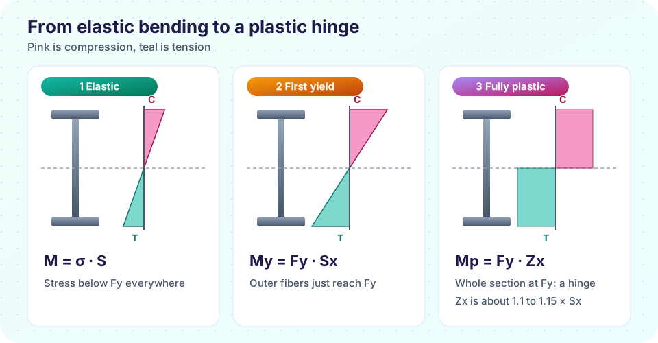
Within the elastic range, bending stress at a distance y from the neutral axis is σ = M y / I. The largest stress is at the outer fibers, σ = M / S where S = I / c and c is half the depth. The beam first yields when this stress hits Fy:
My = Fy × S
For an I-shape of depth d, flange width bf, flange thickness tf and web thickness tw:
I = bf·d³/12 − (bf − tw)·(d − 2tf)³/12
Plastic moment
A ductile beam does not fail at first yield. The flanges keep yielding while the load grows, and the yielded zone spreads inward. At the limit the entire section is at Fy: the top half in compression, the bottom half in tension. The moment of those two equal and opposite forces is
Mp = Fy × Z with Z = bf·tf·(d − tf) + tw·(d − 2tf)² / 4
The ratio Z/S, the shape factor, is about 1.10 to 1.15 for standard I-shapes bent about the strong axis and 1.5 for a rectangle. That 12 percent reserve of strength beyond first yield is what the LRFD flexure check exploits: φMn = 0.90 × Mp for a compact, adequately braced beam.
Compact sections
To reach Mp the flange and web must not buckle locally before yielding. Codes limit the width-to-thickness ratios (bf/2tf and h/tw) of compact sections. Almost every rolled wide-flange shape in a catalog meets these limits for 345 MPa steel, but you must check the table; noncompact and slender shapes have reduced strength.
Lateral-torsional buckling
A beam is like a column on its side: its top flange is in compression. If the flange is not restrained against sideways movement, it can buckle laterally, taking the beam with it in a twisting motion. The strength depends on the unbraced length Lb, giving three zones:
Lb ≤ Lp                Mn = Mp                         (plastic)
Lp < Lb ≤ Lr           linear drop from Mp toward 0.7 Fy Sx    (inelastic LTB)
Lb > Lr                Mn = Fcr × Sx ≤ Mp              (elastic LTB)
with Lp = 1.76 ry √(E/Fy). A concrete floor slab connected to the top flange by studs or by good friction usually gives continuous bracing, so Lb is small and Mn = Mp. A moment-bearing beam in a long run with no bracing may be limited by LTB, and the fix is to add braces. The factor Cb raises the strength for moment diagrams that are not uniform, because the compression flange is not at the maximum stress along the whole length.
Shear
The web carries shear. For rolled shapes with a stocky web the nominal strength is
Vn = 0.6 × Fy × Aw × Cv with Aw = d × tw, φv = 1.00
where Cv = 1 for most rolled shapes. Shear seldom controls except for short, heavily loaded spans and near supports where holes or copes weaken the web.
A complete sizing example
A simply supported floor beam spans 6 m. Dead load 10 kN/m (including self-weight) and live load 15 kN/m. The slab braces the beam continuously.
- Factored load:
wu = 1.2 × 10 + 1.6 × 15 = 36 kN/m. - Maximum moment:
Mu = wu L² / 8 = 36 × 6² / 8 = 162 kN·m. Maximum shear:Vu = wu L / 2 = 108 kN. - Required plastic modulus:
Zreq = Mu / (0.90 Fy) = 162×10⁶ / (0.90 × 345) = 522×10³ mm³. - Deflection under live load alone, limit
L/360 = 16.7 mm: withδ = 5wL⁴/(384EI),Ireq = 75.9×10⁶ mm⁴. - Choose a section with
Z ≥ 522×10³ mm³andI ≥ 75.9×10⁶ mm⁴, then check shear.
Notice that the strength check and the deflection check lead to different required properties: you must satisfy both. For long spans, deflection controls and a deeper section is needed, not a stronger steel.
Common misconceptions
"Mp is reached at the first yield." First yield is My = Fy S. The plastic moment is higher by the shape factor.
"The slab always braces the beam." Only after it is connected and cured. During construction the steel alone carries wet concrete and must be braced or checked with a large Lb.
"High-strength steel reduces deflection." Deflection depends on E and I, not on Fy.
Try it
Press Run (or Ctrl + Enter) to see the result here.
Program input · what you'd type while the program runs
Type the answers before you press Run, one per line. Each time the program reads a line (with input()), it gets the next line from this box.
Check your understanding
Quick check · 5 questions
of 5 answered You scored / 5 · perfect!
-
1. What is the plastic moment of a section?
At the plastic limit the whole section is at Fy, giving Mp = Fy·Z. -
2. A simply supported beam of span 8 m carries a factored load of 20 kN/m. What is Mu?
wL²/8 = 20 × 64 / 8 = 160 kN·m. -
3. What is the main effect of a long unbraced length Lb?
Lateral-torsional buckling reduces flexural strength as Lb grows beyond Lp. -
4. Why is a deeper section, not a higher grade of steel, the fix for excess deflection?
δ ∝ 1/(E·I): increasing I with depth is effective; changing the grade does not change E. -
5. For typical rolled I-shapes about the strong axis, the shape factor Z/S is about
Around 1.10 to 1.15; a rectangle is 1.5.
Summary
My = Fy·S(first yield) andMp = Fy·Z(plastic hinge); design strengthφMn = 0.90 Mpfor compact braced beams.- LTB reduces strength when the unbraced length exceeds
Lp = 1.76 ry √(E/Fy). - Shear:
φVn = 1.00 × 0.6 Fy d twfor stocky rolled webs. - Size a beam for strength (
Z), shear and deflection (I); long spans are governed by deflection.
Track your progress
Create a free account to tick off lessons and pick up where you left off on any device.
of Structural Engineering lessons completed