


















Lesson 22 of 47 · Steel Design
Chapter 5 overview: steel design
A map of structural steel design: how tension members, columns, beams and connections are checked against yielding, buckling and fracture with LRFD.
Steel is the material engineers reach for when they need strength, speed and predictability. It is made in a factory, so its properties are controlled. It is strong in both tension and compression. And it is ductile: it stretches a lot before it breaks, which gives warning and lets a structure redistribute load. This chapter turns the analysis tools of the earlier chapters into design: you will choose sizes and prove they are safe.
What you will learn
- How the load-and-resistance-factor design (LRFD) idea works for steel.
- The four member types in a steel frame and the main limit state of each.
- Why the same steel grade can fail by yielding, buckling or fracture.
- What the five lessons of this chapter cover and how they connect.
Key terms
Limit state: a condition at which a member stops doing its job, such as yielding, buckling or fracture.
LRFD: design so that the factored load effect is no more than the factored resistance, Ru ≤ φRn.
Fy and Fu: the yield stress and the ultimate (tensile) stress of the steel.
Resistance factor φ: a number below 1 that covers uncertainty in strength.
Nominal strength Rn: the strength predicted by the design equation before φ is applied.
The LRFD idea in one line
Earlier chapters showed you how to compute the force in a member from factored loads, for example Pu, Mu or Vu. Design now asks one question for every member and every limit state:
demand ≤ φ × nominal strength
Pu ≤ φPn      Mu ≤ φMn      Vu ≤ φVn
The factored load side already carries a safety margin (a combination such as 1.2D + 1.6L multiplies the loads up). The resistance side then carries its own margin, φ, which is smaller when the failure is sudden or hard to predict. For example, yielding is a gradual and well understood failure and uses φ = 0.90, while fracture of a net section is brittle and uses φ = 0.75. This two-sided margin is why the method is called load and resistance factor design. Another method, allowable stress design (ASD), puts the whole margin on one side as a safety factor Ω. Both give similar answers for typical buildings, and this book uses LRFD throughout.
This course uses the vocabulary and the factors of the widely used AISC 360 specification, in SI units. Other countries use Eurocode 3 or national codes with different factors and formulas for the same ideas. Always design to the code that applies where the building stands, and have your work checked by a licensed engineer.
Steel properties that matter
A typical structural steel for wide-flange shapes has Fy = 345 MPa (50 ksi) and Fu = 450 MPa (65 ksi). Plates and channels are often Fy = 250 MPa. The modulus of elasticity is the same for all steels, E ≈ 200 GPa, so a stronger steel does not make a stiffer beam. That fact is important: when deflection controls, a high-strength steel buys you nothing, only a deeper section does.
The stress-strain curve has four stages: a straight elastic line, a flat yield plateau, a rising strain-hardening stage, and finally necking and fracture. Design usually works up to the end of the plateau, because the plateau is where the material gives plenty of warning.
The four member types
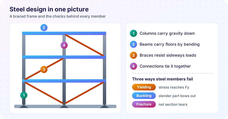
Here is how a frame divides up, as numbered in the picture.
- Columns carry compression, often with bending. Their danger is buckling.
- Beams carry gravity loads by bending and shear. Their dangers are yielding, lateral-torsional buckling and too much deflection.
- Braces (or tension rods) carry axial force from wind and earthquake. A brace is a tension member when it is pulled and a compression member when it is pushed.
- Connections transfer forces from member to member through bolts and welds. A building is usually only as strong as its connections.
Tension members are checked for yield and fracture, compression members for buckling, beams for flexure, shear and deflection, and connections for bolt or weld strength and the strength of the parts they join. Each of the next four lessons takes one of these in turn.
The three families of failure
Yielding means the steel reaches Fy and starts to flow. It is ductile and forgiving, so it gets the highest φ. Buckling is a stability failure: a slender part moves sideways, and strength depends on geometry (length, stiffness, support) rather than on Fy. Fracture is the steel tearing, often at a hole or a weld, and it is the failure you least want because it can be sudden. The design equations deliberately make yielding happen first and fracture last, which is called capacity design thinking.
Steel design in four steps
Repeat until every ratio is below 1
Why φ is below 1
Try it
The first demonstration checks a handful of demand and capacity pairs and prints the demand-capacity ratio, the number every design check ends with.
Press Run (or Ctrl + Enter) to see the result here.
Program input · what you'd type while the program runs
Type the answers before you press Run, one per line. Each time the program reads a line (with input()), it gets the next line from this box.
Press Run (or Ctrl + Enter) to see the result here.
Program input · what you'd type while the program runs
Type the answers before you press Run, one per line. Each time the program reads a line (with input()), it gets the next line from this box.
Check your understanding
Quick check · 4 questions
of 4 answered You scored / 4 · perfect!
-
1. What does the LRFD requirement Ru ≤ φRn say?
Factored loads on the demand side, a reduced nominal strength on the capacity side. -
2. Why is φ for net-section fracture smaller than φ for yielding?
Brittle, sudden failures receive a larger safety margin. -
3. Which property is almost the same for all structural steels?
E is nearly constant, so stronger steel does not give a stiffer beam. -
4. A slender column fails by
Slender compression members bow sideways before the steel reaches its yield stress.
Summary
- Steel design checks
demand ≤ φ × nominal strengthfor every member and limit state. - The three failure families are yielding (ductile, φ = 0.90), buckling (geometry-driven) and fracture (brittle, φ = 0.75 for net sections).
- Typical numbers:
Fy = 345 MPa,Fu = 450 MPa,E = 200 GPa. - Columns, beams, braces and connections each have their own governing limit states.
Next: Tension members
Track your progress
Create a free account to tick off lessons and pick up where you left off on any device.
of Structural Engineering lessons completed