


















Lesson 43 of 47 · Projects and Practice
Project: design a reinforced concrete beam
A guided project: factor loads on a 6 m concrete beam, solve for flexural steel, check ductility and minimum steel, design stirrups and draw the section.
Here is the second project: a concrete floor beam, designed from the loads to the bar layout. Where the steel beam project picked a rolled shape from a list, concrete design has more freedom, because you choose both the cross-section and the number and size of the bars. Your job is to find a layout that is strong, ductile, buildable and economical.
What you will learn
- How to carry a beam design from loads to bar layout.
- How to check ductility, minimum steel and bar fit.
- How to design stirrups using shear at distance d from the support.
- How to document the result.
Key terms
Effective depth d: depth from the top compression fiber to the tension steel's centroid.
Reinforcement ratio ρ: As / (b d).
Bar fit: the check that the bars and stirrups physically fit in the width with cover and spacing.
Critical section: the location, d from the support face, where design shear is taken.
The problem
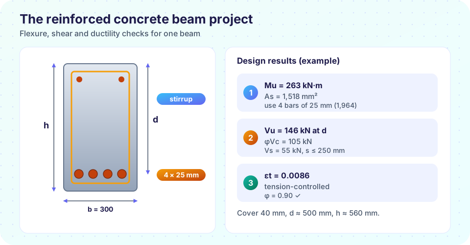
A simply supported beam spans 6 m. It is 300 mm wide and 560 mm deep, with d ≈ 500 mm after 40 mm cover, a 10 mm stirrup and half of a 25 mm bar. Loads: a superimposed dead load of 18 kN/m, a live load of 20 kN/m, and the beam's own weight. Concrete f′c = 30 MPa, steel fy = 420 MPa, stirrups of 10 mm bars with two legs (Av = 157 mm²).
Step 1: factored load
self-weight = 0.30 × 0.56 × 24 = 4.03 kN/m
wu = 1.2 × (18 + 4.03) + 1.6 × 20 = 58.4 kN/m
Step 2: moment and shear
Mu = wu L² / 8 = 58.4 × 36 / 8 = 263 kN·m
Vu(at d = 0.5 m) = wu (L/2 − d) = 58.4 × 2.5 = 146 kN
Step 3: flexural steel
Use the closed-form solution for ρ from the quadratic:
Rn = Mu / (0.90 b d²) = 263×10⁶ / (0.90 × 300 × 500²) = 3.90 MPa
ρ = 0.85 f′c/fy × [1 − √(1 − 2 Rn/(0.85 f′c))] = 0.01012
As = ρ b d = 1,518 mm²
Four 25 mm bars give 1,964 mm². Three 25 mm bars give only 1,473 mm², slightly short; so either four 25 mm bars or a mix such as three 25 mm and one 20 mm (1,787 mm²) is needed.
Check ductility and fit
With As = 1,964 mm²: a = 1,964 × 420 / (0.85 × 30 × 300) = 108 mm, c = a/0.836 = 129 mm, εt = 0.003 × (500 − 129)/129 = 0.0086. This exceeds 0.005, so the section is tension-controlled with φ = 0.90. φMn = 331 kN·m against Mu = 263 kN·m: ratio 0.79.
Fit: the width inside the stirrups is 300 − 2 × 40 − 2 × 10 = 200 mm. Four 25 mm bars take 100 mm, leaving 100 mm for three gaps of 33 mm, above the 25 mm minimum. Minimum steel As,min = 0.00333 × 300 × 500 = 500 mm² is satisfied by far.
Step 4: shear
Vc = 0.17 √30 × 300 × 500 = 139.7 kN       φVc = 104.8 kN < 146 kN: stirrups needed
Vs = 146/0.75 − 139.7 = 55 kN
s = Av fyt d / Vs = 157 × 420 × 500 / 55,000 = 598 mm
The maximum spacing is d/2 = 250 mm (since Vs is below 0.33√f′c bw d = 271 kN), so use 10 mm stirrups at 250 mm. At the support, where shear is largest, many designers place the first stirrup 50 mm from the face and use a closer 150 mm spacing for the first meter: not necessary here, but it is good practice.
Step 5: what is left
- Development: bottom bars must extend into the supports far enough (development length or hooks, see the detailing lesson).
- Deflection:
h = 560 mm ≥ L/16 = 375 mm: passes the minimum thickness table with margin. - Crack control: bars spaced and sized in accordance with code maximum spacing rules.
- Bar cutoffs and top steel: two 12 mm bars at the top hold the stirrups and carry small negative moments at the supports.
Common misconceptions
"The calculated As is the final answer." The calculation gives a minimum; the actual bar layout must satisfy a standard size and fit in the section.
"If φMn is much bigger than Mu the beam is safer." Not necessarily: too much steel raises the risk of a brittle failure. The ductility check is what keeps it honest.
"Stirrups are optional where the calculation shows none are needed." Codes require minimum stirrups in almost all beams.
Try it
Press Run (or Ctrl + Enter) to see the result here.
Program input · what you'd type while the program runs
Type the answers before you press Run, one per line. Each time the program reads a line (with input()), it gets the next line from this box.
Check your understanding
Quick check · 4 questions
of 4 answered You scored / 4 · perfect!
-
1. Where is the design shear taken for this beam?
The critical section is d from the face of the support. -
2. Three 25 mm bars give As = 1,473 mm². Is that enough for the required 1,518 mm²?
1,473 < 1,518, so four bars (or a mix) are needed. -
3. A tension-controlled section has εt of at least
At εt ≥ 0.005 the section is tension-controlled and φ = 0.90. -
4. The maximum stirrup spacing for this beam is
The required spacing is 598 mm, but the maximum allowed is d/2.
Summary
- Factor the load including self-weight:
Mu = wu L²/8, shear atdfrom the support. - Solve
AsfromRnandρ; choose bars; checkεt ≥ 0.005, minimum steel and bar fit. - Stirrups:
s = Av fyt d / Vs, capped atd/2and 600 mm. - Document the result and finish the details: anchorage, top bars, deflection.
Next: Practice problem set
Track your progress
Create a free account to tick off lessons and pick up where you left off on any device.
of Structural Engineering lessons completed