


















Lesson 30 of 47 · Reinforced Concrete
Shear, stirrups and detailing of RC beams
Design shear reinforcement for concrete beams: concrete and stirrup strength, spacing limits, minimum stirrups, plus development length, hooks, cover and minimum depth.
Flexure is the part of beam design that engineers enjoy, because it ends in a clean formula. Shear is messier, and shear failures are dangerous: a beam without enough stirrups can fail suddenly, without much warning, in a diagonal crack that opens near the support. This lesson shows how stirrups work and how to space them, then turns to detailing, the rules for lengths, hooks and cover that make the calculated strength real.
What you will learn
- How shear carries load in a cracked beam, and the truss analogy.
- The equations for
Vc,Vsand the stirrup spacing. - Minimum stirrups, maximum spacing and where the critical section is.
- Development length, hooks, cover and minimum beam depth.
Key terms
Vc: the shear strength the concrete itself supplies.
Vs: the shear strength provided by stirrups.
Av: the area of all stirrup legs crossing a section (2 legs for a simple U or closed stirrup).
Development length ld: the embedded length a bar needs to reach its full yield strength.
Standard hook: a bend (usually 90° or 180°) that anchors a bar in a short space.
Shear and diagonal tension
In a beam, a point near the support feels both bending stress and shear stress. Their combination produces principal tension at an inclined angle. When it exceeds the concrete's tensile strength a diagonal crack forms, typically at about 45 degrees. A beam without stirrups has only the concrete uncracked above the crack, friction on the crack faces and dowel action of the longitudinal bars to resist shear, and the failure can be explosive.
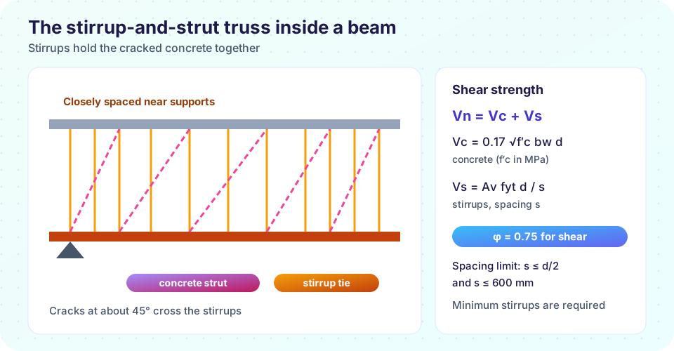
Stirrups cross the crack and provide a tension tie. The truss analogy (Ritter and Mörsch, about 1900) pictures this: the top compression zone is the top chord, the longitudinal steel is the bottom chord, the vertical stirrups are tension members and the cracked concrete between inclined cracks forms diagonal compression struts.
Shear strength equations
The strength design relations (in SI units, with f′c in MPa, dimensions in mm, forces in newtons) are
φVn ≥ Vu          φ = 0.75
Vn = Vc + Vs
Vc = 0.17 λ √f′c bw d          (λ = 1 for normal-weight concrete)
Vs = Av fyt d / s
Vs ≤ 0.66 √f′c bw d            (otherwise enlarge the section)
fyt is the yield strength of the stirrup steel, bw the web width and s the spacing along the beam. Rearranging for spacing:
s = Av fyt d / Vs, with Vs = Vu/φ − Vc
Where is the critical section?
For a beam loaded at the top and supported at the bottom, the concrete near the support is compressed by the reaction, which allows the first inclined crack to form farther in. The design shear can therefore be taken at a distance d from the face of the support. Stirrups are still provided all the way to the support.
Minimum stirrups and maximum spacing
If the shear is greater than half of φVc, the code requires stirrups at least
Av,min / s = max(0.062 √f′c, 0.35) × bw / fyt
Maximum spacing: the smaller of d/2 and 600 mm when Vs ≤ 0.33 √f′c bw d, and half of that otherwise (d/4, 300 mm). These rules make sure that every possible diagonal crack, which spans roughly d along the beam, is crossed by at least one stirrup.
Worked example
Beam: bw = 300 mm, d = 500 mm, f′c = 30 MPa, 10 mm two-leg stirrups (Av = 157 mm², fyt = 420 MPa). Factored shear at distance d from the support: Vu = 180 kN.
Vc = 0.17 × √30 × 300 × 500 = 139.7 kN.φVc = 104.8 kN< 180 kN, so stirrups are required.Vs = 180/0.75 − 139.7 = 100.3 kN.s = 157 × 420 × 500 / 100,300 = 329 mm.- Maximum spacing
d/2 = 250 mm, so uses = 250 mm. - Check the minimum:
Av,min/s = 0.35 × 300/420 = 0.25 mm²/mm, i.e.s ≤ 157/0.25 = 628 mm: fine.
Where the shear falls toward midspan you can increase the spacing, but never beyond the limit.
Detailing: making the strength real
Calculations say how much steel; detailing says where it goes and how it is anchored.
Development length
A bar must be embedded far enough that bond can build up the full yield force. For good spacing and cover, and uncoated bars in normal concrete, a simplified form for tension is
ld = fy / (1.7 λ √f′c) × db     (db ≥ 22 mm)
ld = fy / (2.1 λ √f′c) × db     (db ≤ 19 mm)
For fy = 420 MPa, f′c = 30 MPa a 25 mm bar needs about 45 db, i.e. 1.13 m. Real code has more factors (top bar effect, coatings, spacing) and a longer formula; use the simplified result only when its conditions are met.
Hooks and laps
A standard 90 degree hook shortens the embedment: ldh = 0.24 fy / (λ √f′c) × db, which is about 18 db for the numbers above, and at least 8 db and 150 mm. Bars longer than stock lengths are spliced by lapping, typically at least 1.0 or 1.3 times ld in tension, and laps are staggered away from the points of maximum stress.
Cover and spacing
Cover to stirrups is typically 40 mm for beams exposed to weather and 20 to 30 mm indoors (check the local code). Clear spacing between bars: at least db and 25 mm. Bars must also fit between stirrups, so check the bar layout with real dimensions.
Minimum depth for deflection
A beam can meet the strength check and still sag. For non-prestressed beams, a table lets you skip the deflection calculation if the depth h is at least:
| Support condition | Minimum h |
|---|---|
| Simply supported | L/16 |
| One end continuous | L/18.5 |
| Both ends continuous | L/21 |
| Cantilever | L/8 |
(for fy = 420 MPa and normal-weight concrete; adjust for other steels.)
Common misconceptions
"Stirrups only matter near supports." They run the full length where shear exceeds φVc/2, and also hold bars in place and confine concrete.
"Shear steel adds to the concrete forever." Vc is only reliable while the concrete is not damaged by wide cracks, which is why the code caps Vs.
"A bar can be cut off where moment is zero." It needs to extend past that point by d or 12 db and have development length from its point of maximum stress.
Try it
Press Run (or Ctrl + Enter) to see the result here.
Program input · what you'd type while the program runs
Type the answers before you press Run, one per line. Each time the program reads a line (with input()), it gets the next line from this box.
Press Run (or Ctrl + Enter) to see the result here.
Program input · what you'd type while the program runs
Type the answers before you press Run, one per line. Each time the program reads a line (with input()), it gets the next line from this box.
Check your understanding
Quick check · 5 questions
of 5 answered You scored / 5 · perfect!
-
1. In the truss analogy, the stirrups act as
Stirrups carry tension across the diagonal cracks. -
2. Vc for bw = 250 mm, d = 450 mm, f′c = 25 MPa (λ = 1) is closest to
0.17 × 5 × 250 × 450 = 95.6 kN. -
3. Where is the design shear usually taken for a beam supported from below?
The support reaction compresses the end zone, so the critical section is d from the face. -
4. The maximum stirrup spacing for ordinary shear is the smaller of d/2 and
d/2 and 600 mm when Vs is at most 0.33√f′c bw d. -
5. Development length is the length needed for
The bar must be embedded long enough to anchor its full force.
Summary
Vn = Vc + VswithVc = 0.17√f′c bw d,Vs = Av fyt d/s,φ = 0.75.- Take design shear at
dfrom the support face; space stirrups no farther thand/2(or 600 mm), closer at high shear. - Provide minimum stirrups when
Vu > 0.5φVc. - Detail development lengths, hooks, laps, cover and a minimum depth; strength on paper needs anchorage in the field.
Next: Columns and slabs
Track your progress
Create a free account to tick off lessons and pick up where you left off on any device.
of Structural Engineering lessons completed