


















Lesson 31 of 47 · Reinforced Concrete
Columns and slabs: interaction and one-way design
Design reinforced concrete columns and one-way slabs: axial capacity, tied and spiral columns, the P-M interaction diagram, steel limits, slab thickness and reinforcement.
Beams carry loads sideways; columns carry them down. A floor slab spreads load onto beams and walls. Between them they make up the skeleton of nearly every concrete building. Columns are special because they rarely see pure axial force: wind, unequal spans and eccentric connections add bending, so the right model is a combination of axial load and moment.
What you will learn
- The axial capacity of a short column and why a 0.80 cap is applied.
- How tied and spiral columns differ and what the steel limits are.
- What the interaction diagram means and its three key points.
- How to size a one-way slab and its steel.
Key terms
Gross area Ag: the whole column cross-section.
Ast: total area of longitudinal bars; ρg = Ast / Ag.
Tie: a closed loop of small bar that holds longitudinal bars and prevents them from buckling outward.
Spiral: a continuous helical bar that confines the core and gives greater ductility.
Interaction diagram: the plot of axial capacity against moment capacity for a given section.
Axial capacity of a short column
If concrete and steel both reach their strengths together, the nominal axial capacity under pure axial load is
P0 = 0.85 f′c (Ag − Ast) + fy Ast
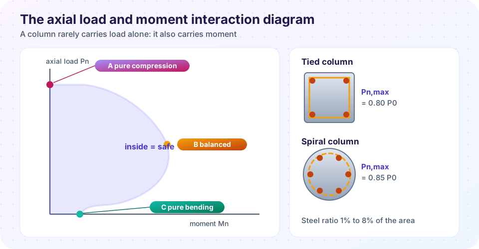
(the concrete area minus the bar area, so the steel space is not counted twice). Real columns are never loaded exactly at the centroid, so codes cap the axial strength for accidental eccentricity: Pn,max = 0.80 P0 for tied columns and 0.85 P0 for spiral columns. The resistance factors are φ = 0.65 (tied) and 0.75 (spiral) for compression-controlled sections, because column failures are brittle and one failed column can bring down a whole structure.
Worked example
A 400 mm × 400 mm tied column has eight 25 mm bars (Ast = 3,928 mm²), f′c = 30 MPa, fy = 420 MPa.
ρg = 3,928/160,000 = 2.46%, within the 1% to 8% range.P0 = 0.85 × 30 × (160,000 − 3,928) + 420 × 3,928 = 5,630 kN.φPn,max = 0.65 × 0.80 × 5,630 = 2,927 kN.
Tied versus spiral
Tied columns have closed ties around the vertical bars at a spacing of at most 16 db, 48 tie diameters or the least column dimension, whichever is smaller. A rectangular column needs at least 4 bars. Spiral columns have a continuous spiral and at least 6 bars. The spiral confines the core, so even after the outer shell spalls off the column keeps carrying load and deforms a lot before failure. That ductility earns the higher φ and the 0.85 cap.
Slender columns
A tall, thin column also buckles, and the second-order moments from its own deflection (the P-Δ effect) add to the design moment. Codes classify a column as short or slender by kLu/r (roughly 22 for a braced column with equal end moments) and give magnification methods for slender ones. Short columns are the most common and the subject here.
The interaction diagram
Add bending to the picture. For each possible neutral-axis depth, strain compatibility gives the stress in every bar and in the concrete block, and from those you compute one axial force Pn and moment Mn. Sweeping the neutral axis from very deep to very shallow traces the curve:
- A, pure compression: the neutral axis is far outside the section,
Mn = 0. - B, balanced point: the concrete crushes (
εc = 0.003) just as the extreme steel yields. Above it, failure is by concrete crushing; below it, by tension steel yielding and ductile behavior. - C, pure bending:
Pn = 0and the capacity is that of a beam.
Between B and C, more axial load actually raises the moment capacity (compression helps close cracks), a surprising and important fact. Above B, more axial load lowers it. A designer plots the factored design curve (φPn, φMn) and checks that the design pair (Mu, Pu) lies inside.
One-way slabs
A slab supported on two opposite edges (or long rectangular panels, with a length-to-width ratio above about 2) bends mainly in the short direction. Design it as a beam 1 m wide.
Thickness. The code lets you skip deflection calculations if h ≥ L/20 (simply supported), L/24 (one end continuous), L/28 (both ends) or L/10 (cantilever) for fy = 420 MPa.
Steel. Flexural steel comes from the same stress block equations as beams. In the other direction place shrinkage and temperature reinforcement of at least 0.0018 × b × h for Grade 420 steel. Maximum spacing of main bars is the smaller of 3h and 450 mm.
Worked example
A simply supported slab spans 4 m. Superimposed dead load 1.5 kPa, live 3 kPa, concrete 24 kN/m³, f′c = 30 MPa, fy = 420 MPa.
h ≥ 4,000/20 = 200 mm. Take 200 mm.- Self-weight
24 × 0.20 = 4.8 kPa.wu = 1.2 × (4.8 + 1.5) + 1.6 × 3.0 = 12.36 kN/mper metre width. Mu = 12.36 × 4² / 8 = 24.7 kN·m/m.- With
d = 165 mm, required steelAs ≈ 405 mm²/m. Minimum steel0.0018 × 1,000 × 200 = 360 mm²/m. - Use 12 mm bars at 250 mm:
452 mm²/m.
Two-way slabs and punching shear
Square panels supported on four sides bend in both directions, and flat plates (slabs on columns without beams) must resist punching shear around each column, where the slab can fail like a cookie cutter. Those topics use design tables, strip methods and special shear reinforcement. They come later in a full course, but the ideas you have learned (stress block, development, minimum steel) all apply.
Common misconceptions
"A column is just a compressed concrete block." Real columns carry moment, and the steel contributes to compression: the interaction diagram, not P0, is the design tool.
"More longitudinal steel without ties is fine." Ties stop the bars from buckling out; spacing rules are as important as steel area.
"A slab is thin, so it needs little steel." Its steel is small per metre, but the thickness often governs by deflection.
Try it
Press Run (or Ctrl + Enter) to see the result here.
Program input · what you'd type while the program runs
Type the answers before you press Run, one per line. Each time the program reads a line (with input()), it gets the next line from this box.
Press Run (or Ctrl + Enter) to see the result here.
Program input · what you'd type while the program runs
Type the answers before you press Run, one per line. Each time the program reads a line (with input()), it gets the next line from this box.
Check your understanding
Quick check · 5 questions
of 5 answered You scored / 5 · perfect!
-
1. The cap Pn,max = 0.80 P0 for tied columns allows for
Real columns are never perfectly centered, so the code limits the pure-compression strength. -
2. What is the allowed range of the longitudinal steel ratio ρg in the code?
Between 1% and 8% of the gross area, with 4% being a practical maximum for congestion. -
3. In the interaction diagram, point B (balanced) is where
At the balanced point εc = 0.003 and the extreme steel reaches its yield strain together. -
4. Minimum thickness of a simply supported one-way slab of span 4.2 m (fy = 420 MPa)?
L/20 = 4,200/20 = 210 mm. -
5. Why does a spiral column earn a higher φ than a tied column?
Confinement keeps the column carrying load after the shell spalls.
Summary
- Short column:
P0 = 0.85 f′c (Ag − Ast) + fy Ast; designφPn,max = φ × 0.80 P0(tied) or0.85 P0(spiral). - Steel ratio 1% to 8%; ties or spirals keep bars in place and confine concrete.
- The interaction diagram shows all combinations of load and moment a column can carry.
- One-way slab: thickness from
L/20toL/28, flexural steel by the stress block, plus shrinkage steel0.0018 b h.
Next: Chapter 6 review
Track your progress
Create a free account to tick off lessons and pick up where you left off on any device.
of Structural Engineering lessons completed