


















Lesson 21 of 47 · Indeterminate Structures
Chapter 4 review: indeterminate structures
Review the degree of indeterminacy, the force method, moment distribution and the matrix stiffness method, with a comparison table, a stiffness experiment and a ten-question quiz.
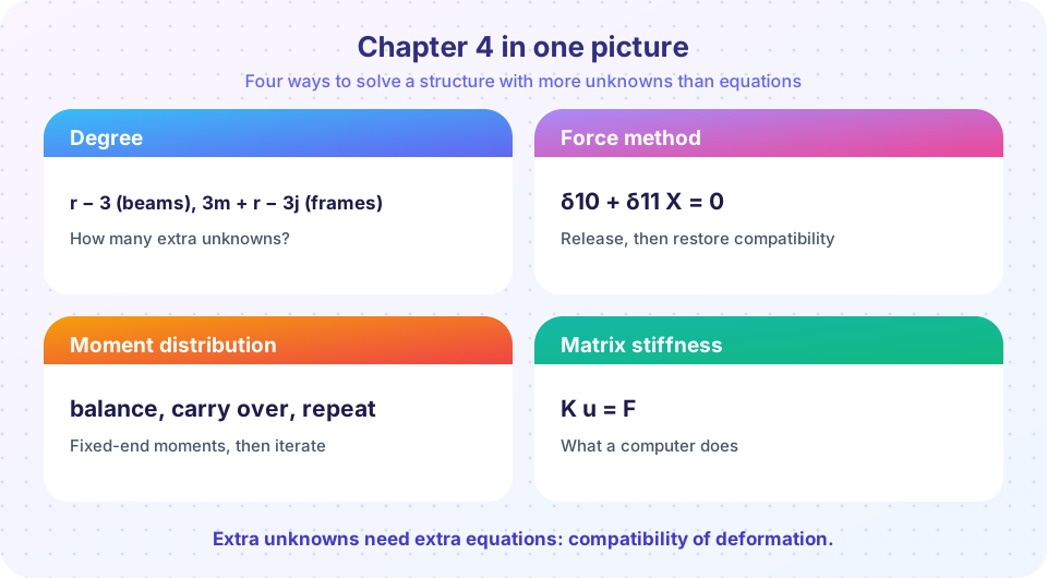
This chapter added the missing piece of structural analysis: when equilibrium is not enough, compatibility of deformation supplies the extra equations, and the stiffness of the members decides how the load is shared. You met three methods that reach the same answers by different routes. This review compares them, then lets you experiment with stiffness.
What you will learn
- When to choose each of the three methods.
- Why relative stiffness controls how moment is shared.
- Whether you can recognize and verify an indeterminate result.
Chapter in one table
| Lesson | Method | Best for | Cost |
|---|---|---|---|
| Overview | Degree = 3m + r − 3j − c; m + r − 2j for trusses | Deciding how hard the problem is | Counting only |
| Force method | Release redundants; δ10 + f11 X = Δ | One or two redundants; settlement; understanding | Hand work grows fast with redundants |
| Moment distribution | FEM, DF, carry-over, iterate | Continuous beams and non-sway frames by hand | Many cycles for big frames |
| Matrix stiffness | K u = F | Everything, by computer | Needs software or code |
Results to remember
| Structure (uniform load w, span L) | Result |
|---|---|
| Propped cantilever | RB = 3wL/8, RA = 5wL/8, MA = wL²/8, M⁺max = 9wL²/128 |
| Fixed-fixed beam | End moments wL²/12, midspan moment wL²/24 |
| Two equal spans | Middle support 5wL/4, ends 3wL/8, hogging wL²/8 |
| Simple beam (for comparison) | Midspan moment wL²/8 |
Checklist for an indeterminate analysis
- Count the degree of indeterminacy and decide on a method.
- Idealize supports and joints; decide whether settlement or temperature matters.
- Solve: compatibility (force method), balance and carry-over (moment distribution) or K u = F.
- Check equilibrium: reactions must sum to the total load, joints must balance.
- Check plausibility: compare with the simple-beam value wL²/8 and the fixed-end value wL²/12, which bracket most moments.
- Check limiting cases: infinite support stiffness, zero stiffness, symmetry.
Try it
Press Run (or Ctrl + Enter) to see the result here.
Program input · what you'd type while the program runs
Type the answers before you press Run, one per line. Each time the program reads a line (with input()), it gets the next line from this box.
The hogging moment over B moves between two limits: wL₁²/8 = 45 kN·m when the longer span is very stiff and wL₂²/8 = 80 kN·m when it is very flexible. Changing one member size changes the moments in its neighbours, which is why a designer can no longer choose member sizes independently once the structure is indeterminate.
Press Run (or Ctrl + Enter) to see the result here.
Program input · what you'd type while the program runs
Type the answers before you press Run, one per line. Each time the program reads a line (with input()), it gets the next line from this box.
Common misconceptions
"The three methods give different answers." They solve the same equations and give the same results; only the arithmetic differs. If they disagree, one has an error.
"Fixed supports are the same as pins with a little moment." A fixed support also prevents rotation, which can double the stiffness of a member and change the load sharing completely.
"If the moment at a support is hogging, the beam is wrong." Hogging over interior supports is normal in continuous beams; reinforcement goes in the top face there.
Check your understanding
Quick check · 10 questions
of 10 answered You scored / 10 · perfect!
-
1. A frame has m = 4, j = 5, r = 5, c = 0. Its degree of indeterminacy is
3m + r − 3j − c = 12 + 5 − 15 = 2. -
2. In the force method, the compatibility equation for a rigid prop is
The displacement at the released support, with X applied, must vanish. -
3. The propped cantilever's fixed-end moment under uniform load is
MA = wL²/2 − (3wL/8)L = wL²/8. -
4. Fixed-fixed beam, w = 24 kN/m, L = 5 m. End moment?
wL²/12 = 24 × 25 / 12 = 50 kN·m. -
5. In moment distribution, the distribution factors at a joint always
They are shares of the unbalanced moment, so they add to 1. -
6. In K u = F, what is K?
K is the global stiffness matrix assembled from the element matrices. -
7. If a support of a continuous beam settles, its reaction
The settling support sheds load to its neighbors. -
8. What is true of the stiffness of a member with a pinned far end?
Releasing the far end rotation makes the member more flexible: 3EI/L. -
9. Which structure has the smallest midspan moment for the same uniform load and span?
The maximum sagging moments are wL²/8 = 0.125wL², 9wL²/128 ≈ 0.070wL² and wL²/24 ≈ 0.042wL². The fixed-fixed beam has the smallest. -
10. Why are results from software still checked by hand?
A model error is invisible to the solver; simple hand estimates catch it.
Summary
- Indeterminate analysis adds compatibility to equilibrium; forces then depend on member stiffness.
- Force method: release redundants and restore displacement; moment distribution: balance and carry over; matrix stiffness: assemble and solve K u = F.
- Key results: propped cantilever 3wL/8 and wL²/8; fixed-fixed wL²/12 and wL²/24; two equal spans 5wL/4 at the middle.
- Settlement and relative stiffness change the moments even when the loads are the same.
- Always check equilibrium, limiting cases and the simple-beam bracket.
Track your progress
Create a free account to tick off lessons and pick up where you left off on any device.
of Structural Engineering lessons completed