


















Lesson 12 of 47 · Transmission Lines
Line Parameters: Resistance, Inductance and Capacitance
Calculate the resistance, inductance and capacitance of a three-phase transmission line from its geometry using GMD, GMR and bundled conductors, with a worked 400 kV example.
To analyze a line you need four numbers per kilometer: the series resistance R, the series reactance X, and the shunt susceptance B (plus a tiny leakage conductance that is almost always ignored). This lesson derives all three from the physical layout of the conductors. The recipe looks like a pile of logarithms, but each formula follows from one idea: current produces magnetic flux, and charge produces electric flux, and geometry decides how much.
What you will learn
- What determines the resistance of a line and why ac resistance exceeds dc resistance.
- How to compute inductance using GMD and GMR, including bundled conductors.
- How to compute capacitance and charging current.
- How to turn the results into per-kilometer
R,X,Band the characteristic impedance.
Key terms
- GMD (geometric mean distance): the effective spacing between phases, the cube root of the product of the three spacings.
- GMR (geometric mean radius), Ds: the effective radius of a conductor for inductance;
0.7788 rfor a solid round conductor. - Bundle: two to four subconductors per phase held a fixed distance
dapart. - Transposition: swapping conductor positions along the line so each phase sees the same average geometry.
- Skin effect: ac current crowding toward the surface of a conductor, raising its resistance.
Resistance
The dc resistance of a conductor is R = ρ l / A, where ρ is the resistivity, l the length and A the cross-section. For stranded ACSR conductors the length of each strand is slightly longer than the line itself because of the spiral, which adds a few percent.
Three things make the ac resistance higher than the dc value:
- Skin effect: at 50 or 60 Hz, current crowds toward the surface in large conductors.
- Temperature: for aluminum,
R2 = R1 [1 + α (T2 − T1)]withα ≈ 0.004per °C. A conductor at 75°C has about 22% more resistance than at 20°C. - Proximity effect and strand spiralling: smaller contributions.
Manufacturers publish ac resistance at standard temperatures in conductor tables, and engineers use those tables rather than calculating from scratch. Typical values for the conductors of high-voltage lines are 0.02 to 0.1 Ω/km.
Inductance
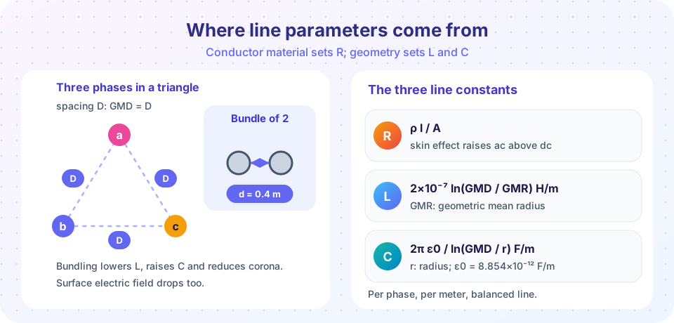
A current in a conductor creates a magnetic field that links the other conductors and the conductor itself. The inductance of one phase of a balanced, transposed three-phase line is
L = 2×10⁻⁷ × ln(GMD / Ds) H/m
Ds is the geometric mean radius, a fictitious radius that accounts for the flux inside the conductor: for a solid round wire Ds = r e^(−1/4) = 0.7788 r, and for stranded conductors it is published in tables.
For three conductors with spacings D12, D23, D31, the geometric mean distance is
GMD = (D12 × D23 × D31)^(1/3)
Bundled conductors. Each phase consists of n subconductors, with d the spacing. Replace Ds with a bundle GMR:
- Two conductors:
Ds,b = √(Ds × d) - Three conductors (triangle):
Ds,b = (Ds × d²)^(1/3) - Four conductors (square):
Ds,b = 1.09 × (Ds × d³)^(1/4)
Because Ds,b is much larger than Ds, the inductance falls. Bundling also lowers the surface electric field, which reduces corona.
Capacitance
Charges on the conductors create an electric field between phases and between each phase and ground. For a balanced transposed line, the capacitance to neutral is
C = 2π ε0 / ln(GMD / r) F/m, with ε0 = 8.854×10⁻¹² F/m
This uses the actual radius r (the electric field is outside the conductor, so there is no internal term). For a bundle, replace r by an equivalent radius with the same formulas as for Ds,b, using r in place of Ds. The ground raises the capacitance slightly; the formula above is accurate enough for most studies.
Reactance and susceptance at frequency f follow directly: X = 2π f L, B = 2π f C. The line charging current per phase is Ic = ω C Vph per unit length. In a lightly loaded line this current is what raises the receiving-end voltage (the Ferranti effect).
Worked example: a 400 kV line
A 400 kV line has a horizontal configuration with phases 9 m apart. Each phase is a bundle of two conductors of radius 1.5 cm, spaced 0.4 m apart. Take the conductor GMR to be 0.7788 × 1.5 cm = 1.168 cm, and a frequency of 50 Hz.
GMD = (9 × 9 × 18)^(1/3) = 1458^(1/3) = 11.34 m.- Bundle GMR
Ds,b = √(0.01168 × 0.4) = 0.0684 m. L = 2×10⁻⁷ × ln(11.34 / 0.0684) = 2×10⁻⁷ × 5.111 = 1.022 µH/m = 1.022 mH/km.X = 2π × 50 × 1.022×10⁻³ = 0.321 Ω/km.- Bundle radius for capacitance:
rb = √(0.015 × 0.4) = 0.0775 m. C = 2π × 8.854×10⁻¹² / ln(11.34 / 0.0775) = 5.563×10⁻¹¹ / 4.986 = 11.16 nF/km.B = 2π × 50 × 11.16×10⁻⁹ = 3.50 µS/km.- Characteristic impedance
Zc = √(L/C) = √(1.022×10⁻⁶ / 1.116×10⁻¹¹) = 303 Ω.
Compare with a single conductor of the same radius: the inductance would be about 2×10⁻⁷ × ln(11.34/0.01168) = 1.375 mH/km and X = 0.43 Ω/km. The bundle drops the reactance by roughly a quarter and raises the capacitance.
Common misconceptions
- "Inductance depends on the current." In the linear range the inductance of a line depends only on the geometry, not on the current. Current only sets the flux.
- "Bundling is just to carry more current." It also cuts the reactance, reduces corona and radio noise, and raises SIL.
- "GMR equals the real radius." The GMR accounts for internal flux and is smaller than
r(about 78% for a solid conductor).
Try it
First, compute L, X, C, B and Zc for the worked example, then see how the reactance and characteristic impedance change with bundle spacing. The code applies the formulas of this lesson.
Press Run (or Ctrl + Enter) to see the result here.
Program input · what you'd type while the program runs
Type the answers before you press Run, one per line. Each time the program reads a line (with input()), it gets the next line from this box.
Second, an interactive line designer. Choose the phase spacing, the number of subconductors and their spacing, and read off X, B, Zc and the surge impedance loading at 400 kV. It uses the same equations for a horizontal arrangement with spacing D.
Check your understanding
Quick check · 5 questions
of 5 answered You scored / 5 · perfect!
-
1. Three phases are spaced 4 m, 4 m and 8 m apart. What is the GMD?
GMD = (4 × 4 × 8)^(1/3) = 128^(1/3) = 5.04 m. -
2. What is the GMR of a solid round conductor of radius r?
Including the internal flux, Ds = r e^(−1/4) = 0.7788 r. -
3. Bundling the phase conductors does which of the following?
A bundle has a larger effective radius, so L falls and C rises. -
4. An aluminum conductor has R = 0.05 Ω/km at 20 °C. Estimate its resistance at 70 °C (α = 0.004 per °C).
R = 0.05 × [1 + 0.004 × 50] = 0.05 × 1.2 = 0.060 Ω/km. -
5. A line has L = 1.0 mH/km and C = 11 nF/km. About what is its characteristic impedance?
Zc = √(L / C) = √(1.0×10⁻³ / 11×10⁻⁹) = √(90,909) ≈ 301 Ω.
Summary
R = ρ l / A, adjusted upward for skin effect and temperature.L = 2×10⁻⁷ ln(GMD / Ds)H/m andC = 2π ε0 / ln(GMD / r)F/m for a balanced, transposed line.- Bundling replaces
Dsandrby larger equivalent radii: less reactance, more capacitance, less corona. X = 2π f L,B = 2π f C,Zc = √(L / C); a 400 kV example gives about 0.32 Ω/km, 3.5 µS/km and 300 Ω.
Next: Short and Medium Lines
Track your progress
Create a free account to tick off lessons and pick up where you left off on any device.
of Electric Power Systems lessons completed