


















Lesson 2 of 47 · Getting Started
The Grid at a Glance: From Power Plant to Socket
Follow electricity from generator to socket: voltage levels, the roles of transmission and distribution, why high voltage saves energy, and how loads shape the system.
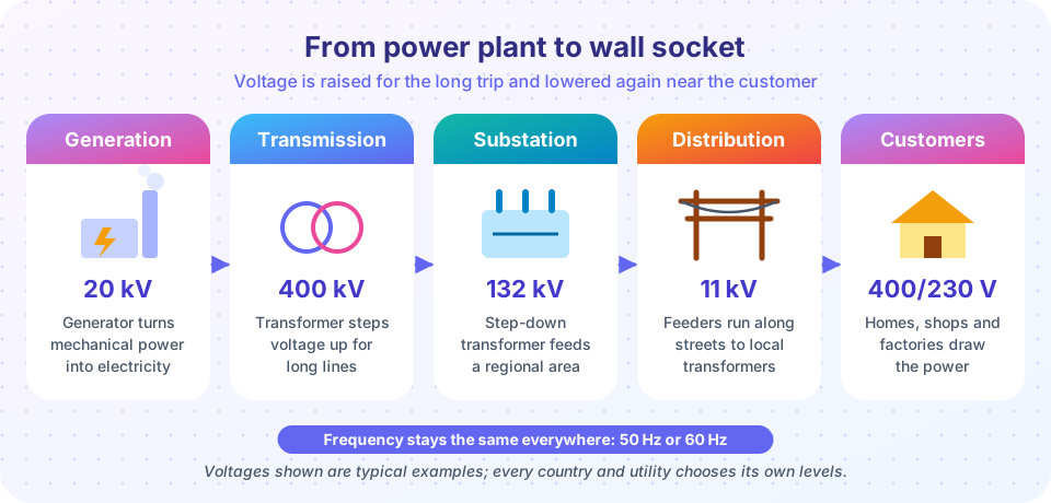
Every electric power system, in every country, has the same basic shape. Large machines called generators produce electricity at a moderate voltage. Transformers raise the voltage so the power can travel long distances on lines. Near towns, other transformers lower the voltage in steps until it is safe for homes and factories. Understanding why the system takes this shape is the foundation for everything that follows.
What you will learn
- The four functional parts of a power system and their typical voltages.
- Why transmission uses high voltage, shown with a loss calculation.
- What makes a system synchronous and why frequency matters.
- How loads and interconnections shape the design.
Key terms
- Transmission: bulk, long-distance transport at high voltage, usually 110 kV and above.
- Distribution: delivery to local customers at medium and low voltage.
- Substation: a site with transformers and switchgear where voltage changes or lines meet.
- Busbar: a heavy conductor inside a substation where several circuits join.
- Interconnection: a link that lets neighboring grids exchange power.
The four parts
Generation. Power plants convert another energy form into electricity: the heat of burning fuel or splitting atoms, the motion of water or wind, or sunlight directly. Most large generators are synchronous machines (chapter 2) that produce three-phase voltage at 10 to 25 kV.
Transmission. A step-up transformer at the plant raises the voltage to hundreds of kilovolts. Typical classes are 110 to 150 kV, 220 to 400 kV and, for the longest routes, 500 to 765 kV. Lines are mostly overhead on towers because air is a free and self-healing insulator. The network is a mesh: many lines join at substations, so power has several routes.
Distribution. Substations lower the voltage to 11 to 33 kV for feeders that run through towns. Small pole or pad-mounted transformers then drop it to 400/230 V (or 208/120 V in North America) for customers. Distribution is usually radial, like branches of a tree, which is cheaper but has less redundancy.
Load. Loads fall into residential, commercial and industrial groups. Households use lighting, heating and electronics; factories use large motors and furnaces. The mix matters because motors and transformers draw reactive power, a topic you will meet in lesson 4 of this chapter.
Why high voltage?
For a three-phase line carrying power P at line voltage V and power factor 1, the current in each conductor is
I = P / (√3 × V)
and the resistive loss in the line, if each conductor has resistance R, is
Ploss = 3 × I² × R
Take P = 100 MW and R = 10 Ω per conductor. At 132 kV the current is about 437 A and the loss is about 5.7 MW. At 400 kV the current is about 144 A and the loss is about 0.62 MW. Tripling the voltage cut the loss by a factor of nine. The same copper, the same power: the only change is the voltage.
This is the single most important economic fact in the system. Higher voltage needs bigger insulators and taller towers, so there is an optimum voltage for each distance and power level. Long, heavy routes justify 400 kV or more; a village feeder is happy at 11 kV.
Frequency and synchronism
Every generator on a grid spins in lockstep with every other, so they all produce voltage at the same frequency: 50 Hz in most of the world and 60 Hz in the Americas and parts of Asia. This is a synchronous system. If one machine tries to speed up, the electrical forces between machines pull it back; the grid acts like a stiff mechanical coupling.
Frequency also acts as a signal. When demand exceeds supply, the rotating machines slow slightly and frequency falls. When supply exceeds demand, frequency rises. Operators keep it within a narrow band, such as 50 Hz plus or minus 0.2 Hz, and chapter 6 shows how.
Two large neighboring grids can be joined by an AC link (and then must synchronize) or by a high-voltage direct current (HVDC) link, which transfers a chosen amount of power without tying their frequencies together. Many undersea cables use HVDC.
Common misconceptions
- "Power flows along the shortest path." In a meshed AC network, power divides among all paths in inverse proportion to their impedance, like water in parallel pipes. This is why a single line trip can overload a distant one.
- "The utility sends voltage and current to a house like a delivery." Voltage is held roughly constant by the system; the customer's load decides how much current flows.
- "Higher voltage means more power is lost." The opposite: higher voltage is how losses are reduced.
Try it
The first example plots the loss for the same 100 MW transmission at different voltages. It assumes a unity power factor and a fixed conductor resistance, which is a simplification: real lines have a different conductor size at each voltage class.
Press Run (or Ctrl + Enter) to see the result here.
Program input · what you'd type while the program runs
Type the answers before you press Run, one per line. Each time the program reads a line (with input()), it gets the next line from this box.
The second example is a calculator. Drag the sliders to see how the voltage level, power and conductor resistance change current and loss. It applies the formulas above and nothing more.
Check your understanding
Quick check · 4 questions
of 4 answered You scored / 4 · perfect!
-
1. A three-phase line carries 60 MW at 220 kV and power factor 1. About what is the current in each conductor?
I = P / (√3 V) = 60e6 / (1.732 × 220e3) = 157.5 A. -
2. If the transmission voltage is doubled for the same power and the same conductors, the resistive loss becomes:
Current halves, and loss is proportional to current squared, so the loss falls to one quarter. -
3. What does a falling grid frequency indicate?
When demand is greater than supply, the rotating machines slow down slightly and the frequency drops. -
4. Why is distribution usually radial?
A radial feeder is cheap and easy to protect but a fault can cut off every customer downstream.
Summary
- A power system has generation, transmission, distribution and load.
- Transformers raise voltage for long trips and lower it near customers.
- For fixed power,
I = P / (√3 V)and loss3 I² R, so loss falls with the square of voltage. - All machines in a synchronous grid share one frequency; frequency signals the supply-demand balance.
- Transmission is a mesh; distribution is usually radial.
Next: Three-Phase Power
Track your progress
Create a free account to tick off lessons and pick up where you left off on any device.
of Electric Power Systems lessons completed