


















Lesson 7 of 47 · Generation and the Grid
Synchronous Generators: From Shaft to Three-Phase Voltage
Learn how a synchronous generator works: speed and frequency, the per-phase equivalent circuit, excitation and reactive power, and the power-angle equation.
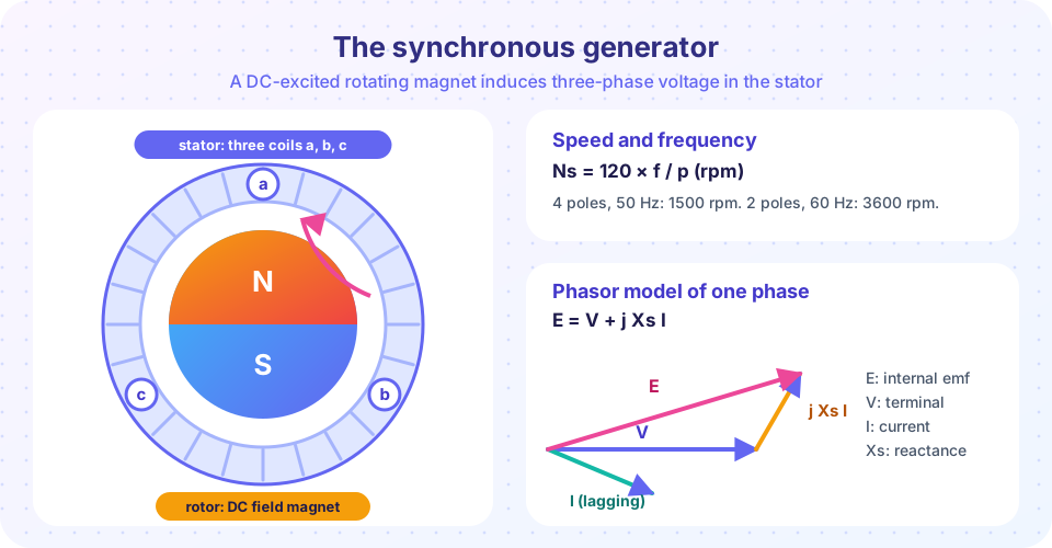
Almost all the electricity in the world is made by synchronous generators. A turbine spins a magnet called the rotor; the magnet's moving field induces voltage in three sets of coils on the stator; those coils deliver three-phase power to the grid. The machine is called synchronous because the rotor turns in exact step with the rotating magnetic field of the stator currents, and therefore with every other machine on the grid.
What you will learn
- How rotor speed, pole count and frequency are tied together.
- How to use the per-phase equivalent circuit
E = V + j Xs I. - How field current (excitation) controls reactive power and voltage.
- The power-angle equation and the limit it implies.
Key terms
- Rotor: the rotating part, carrying the DC field winding that makes the magnet.
- Stator: the stationary part holding the three-phase armature windings.
- Excitation: the DC field current that sets the strength of the magnet.
- Synchronous reactance (Xs): the combined effect of armature reaction and leakage, modeled as a reactance.
- Power angle (δ): the angle between the internal voltage
Eand the terminal voltageV.
Speed, poles and frequency
The rotating field has p poles. In one revolution it sweeps past each coil p/2 times, so the electrical frequency is f = p × N / 120 with N in rpm, or equivalently
Ns = 120 × f / p
A two-pole steam turbine generator at 50 Hz runs at 3000 rpm; at 60 Hz it runs at 3600 rpm. A hydro generator driven by a slow water turbine may have 48 poles and run at 125 rpm at 50 Hz. Machines with round rotors (few poles, high speed) suit steam and gas turbines. Machines with salient poles (many poles, low speed, large diameter) suit hydro.
Voltage and the equivalent circuit
By Faraday's law, the rms voltage induced per phase is proportional to frequency, flux and turns: E = 4.44 f N Φ kw, where kw is a winding factor slightly below 1. Strengthening the field (more Φ) raises E.
When the machine delivers current I, the stator current's own field and leakage reduce the voltage at the terminals. We fold both effects into the synchronous reactance Xs, giving the per-phase equivalent circuit
E = V + (Ra + j Xs) I
Here E is the internal voltage (set by excitation), V is the terminal voltage (set by the grid) and Ra is the small armature resistance. In large machines Ra is much smaller than Xs and is often ignored, leaving E = V + j Xs I.
Worked example
A 50 MVA, 13.8 kV three-phase generator has Xs = 2.5 Ω per phase and delivers 40 MW at power factor 0.8 lagging to a grid held at its rated voltage.
- Phase voltage
V = 13800 / √3 = 7967 V, taken as reference at 0°. - Current:
S = 40 / 0.8 = 50 MVA, soI = 50×10⁶ / (√3 × 13800) = 2092 A, at an angle−36.9°(lagging). j Xs I = 2.5 × 2092 ∠(90° − 36.9°) = 5230 ∠53.1° V = 3138 + j4184 V.E = 7967 + 3138 + j4184 = 11105 + j4184 V, so|E| = 11,867 Vper phase (20.6 kV line-to-line) andδ = 20.6°.
The internal voltage is much higher than the terminal voltage because the machine must also push current through its reactance.
Excitation and reactive power
On a strong grid, a generator cannot choose its terminal voltage; the grid does. It can choose its real power (by turbine torque) and its internal voltage E (by field current). The result:
- Over-excited (high
E): the machine supplies reactive power to the grid (lagging current). It acts like a capacitor, raising the nearby voltage. - Under-excited (low
E): the machine absorbs reactive power from the grid.
This is how generators regulate voltage. An automatic voltage regulator (AVR) adjusts the field current to hold the terminal voltage or the reactive output at a setpoint.
Power and the power angle
Neglecting Ra, the three-phase real power delivered is
P = 3 × (E × V / Xs) × sin δ
(with phase voltages), and the reactive power is Q = 3 × V × (E cos δ − V) / Xs. The maximum real power occurs at δ = 90°: Pmax = 3 E V / Xs. In the example, Pmax = 3 × 11867 × 7967 / 2.5 = 113.5 MW, so the machine is operating well inside its limit at 40 MW (sin δ = 0.35).
Pushing the turbine harder increases δ. Past 90° the rotor can no longer be held in step and the machine loses synchronism: it slips relative to the grid. Chapter 6 studies how the angle behaves after disturbances.
Common misconceptions
- "Raising the field current raises the real power." On a grid, the field current mainly changes reactive power. Real power is set by the turbine torque (the steam, water or fuel valve).
- "The terminal voltage is the same as E." E is the internal (open-circuit) voltage. Under load the terminal voltage differs by the drop across the synchronous reactance.
- "A generator spinning at the wrong speed gives the wrong voltage." Speed sets frequency. When connected to a grid, speed is fixed by the grid. Voltage is set by excitation.
Try it
First, draw the phasor diagram of the worked example and print the numbers. The code uses complex arithmetic exactly as in the hand calculation.
Press Run (or Ctrl + Enter) to see the result here.
Program input · what you'd type while the program runs
Type the answers before you press Run, one per line. Each time the program reads a line (with input()), it gets the next line from this box.
Second, plot the power-angle curve for this machine and mark the operating point. The curve shows the steady-state limit at 90 degrees.
Press Run (or Ctrl + Enter) to see the result here.
Program input · what you'd type while the program runs
Type the answers before you press Run, one per line. Each time the program reads a line (with input()), it gets the next line from this box.
Third, experiment with excitation. The machine delivers a fixed real power into a stiff grid. Change the internal voltage and watch the reactive power and the angle. It uses the equations above with Ra = 0.
Check your understanding
Quick check · 5 questions
of 5 answered You scored / 5 · perfect!
-
1. A 6-pole synchronous generator feeds a 60 Hz grid. What is its speed?
Ns = 120 × 60 / 6 = 1200 rpm. -
2. On a strong grid, what mainly controls the reactive power output of a synchronous generator?
Excitation sets E; a higher E makes the machine supply reactive power. Turbine torque sets real power. -
3. At what power angle is the steady-state maximum power reached (with Ra neglected)?
P = (3 E V / Xs) sin δ is largest at δ = 90°. -
4. Per phase, V = 8 kV, E = 12 kV, Xs = 2 Ω and δ = 30°. What is the real power for all three phases?
P = 3 × (12000 × 8000 / 2) × 0.5 = 72 MW. -
5. What does an under-excited generator do?
With a low E the machine draws reactive power from the grid, like an inductor would.
Summary
- Speed and frequency:
Ns = 120 f / p; on a grid, speed is locked to the grid. - Per-phase model:
E = V + (Ra + j Xs) I. - Excitation controls reactive power and voltage; turbine torque controls real power.
P = 3 E V sin δ / Xs, with the steady-state limit atδ = 90°.- Over-excited machines export reactive power; under-excited ones import it.
Track your progress
Create a free account to tick off lessons and pick up where you left off on any device.
of Electric Power Systems lessons completed