


















Lesson 42 of 47 · Projects and Practice
Project 1: fault study of a three-bus system
Run a complete short-circuit study: build the bus admittance and impedance matrices, compute fault currents and voltages, check breaker ratings and test network changes.
Utilities run fault studies every time they add a generator, a line or a customer, because each change alters the fault level, and the fault level decides whether the breakers and bus bars already installed are still safe. Hand methods (Thevenin equivalents, series-parallel reduction) work for a few buses. For anything bigger, engineers use the bus impedance matrix Zbus: invert the admittance matrix once, and every bus's fault current and every post-fault voltage can be read straight from it.
In this project you study a three-bus 33 kV network with two generators. You will build the matrices, compute three-phase fault currents, trace how current divides, check a breaker's ratings and test what happens when the network changes.
What you will learn
- Build
YbusandZbusfor a small network with generators as sources behind reactance. - Compute three-phase fault current at each bus and the voltages during the fault.
- Trace the contributions of generators and the flow in each line.
- Check interrupting and making ratings, including DC offset.
- Test the effect of network changes on fault levels.
Key terms
Ybus: the bus admittance matrix; element Yii is the sum of admittances connected to bus i, and Yij is minus the admittance between buses i and j.
Zbus: the inverse of Ybus. Zkk is the Thevenin impedance seen at bus k.
Prefault voltage: voltage before the fault, here 1.0 pu everywhere (no load).
Interrupting (breaking) rating: the largest symmetrical rms fault current a breaker can open.
Making rating: the largest peak current a breaker can close onto.
The system and the method
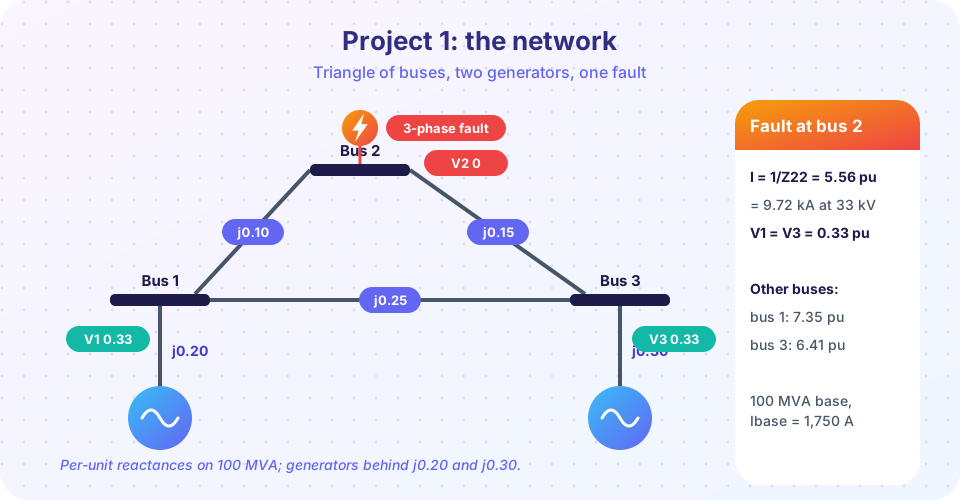
All values are per unit on 100 MVA and 33 kV, so Ibase = 100 MVA/(√3 × 33 kV) = 1,750 A. Generators are represented by an emf of 1.0 pu behind a subtransient reactance (j0.20 at bus 1, j0.30 at bus 3). The lines have reactances j0.10 (1 to 2), j0.15 (2 to 3) and j0.25 (1 to 3). Loads are neglected, which is standard for a short-circuit study because fault currents greatly exceed load currents.
Step 1: Ybus. Each reactance x contributes an admittance y = 1/(jx) to the diagonal elements of its two buses and −y to the off-diagonals. A generator reactance contributes only to its own bus (the other end is ground).
Y11 = 1/j0.20 + 1/j0.10 + 1/j0.25 = −j19.0
Y22 = 1/j0.10 + 1/j0.15            = −j16.67
Y33 = 1/j0.30 + 1/j0.15 + 1/j0.25 = −j14.0
Y12 = +j10,   Y23 = +j6.67,   Y13 = +j4
Step 2: Zbus. Inverting the matrix gives
Zbus = j × [ 0.136  0.120  0.096 ]
           [ 0.120  0.180  0.120 ]
           [ 0.096  0.120  0.156 ]
The diagonal Zkk is the impedance you would see looking into bus k with the generators' emfs shorted. The off-diagonal Zik says how much the voltage at bus i falls per unit of current injected at k.
Step 3: fault at bus k. A bolted three-phase fault at bus k is a current If = Vprefault/Zkk leaving the bus, and the post-fault voltage at any bus i is
Vi = 1 − Zik / Zkk
For a fault at bus 2: If = 1/0.18 = 5.56 pu = 9.72 kA, and V1 = 1 − 0.12/0.18 = 0.333, V3 = 0.333, V2 = 0.
Step 4: who supplies the fault? Generator 1 supplies (1 − V1)/j0.20 = 0.667/0.20 = 3.33 pu and generator 3 supplies 0.667/0.30 = 2.22 pu; the sum is 5.56 pu, as it must be. In the lines, I12 = (V1 − V2)/0.10 = 3.33 pu and I32 = (V3 − V2)/0.15 = 2.22 pu. The line from bus 1 to bus 3 carries nothing, because V1 = V3. The reason is that the "bridge" formed by the two generators and the two lines is balanced (0.20/0.10 = 0.30/0.15), so the diagonal line has no voltage across it. This is a nice check: the answer you would get by ignoring that line must equal 0.30 || 0.45 = 0.18, and it does.
Step 5: breaker check. The fault current is 9.72 kA at bus 2, 12.86 kA at bus 1 (7.35 pu) and 11.22 kA at bus 3 (6.41 pu). A standard 12.5 kA breaker (breaking), with a making rating of 31.5 kA peak, would be marginal at bus 1. The first peak includes DC offset: with an X/R ratio of 10, κ = 1.02 + 0.98·e^(−3/10) = 1.746 and the peak at bus 1 is κ·√2·12.86 = 31.8 kA, which exceeds 31.5 kA. The conclusion: bus 1 needs the next rating (16 kA breaking, 40 kA making), or a fault-current limiter, or a network change such as larger generator reactance.
Step 6: extensions. Unbalanced faults need three networks. The sequence Zbus matrices for positive, negative and zero sequence are built in the same way, with Z0 values for lines and transformers connection types; then Ia = 3E/(Z11 + Z22 + Z00) for a single line-to-ground fault at bus k (Z11, Z22, Z00 meaning the diagonal elements of the three matrices for that bus). Commercial programs do exactly this for thousands of buses.
Common misconceptions
"A fault current is limited by the load." It is limited by the network and source reactances; the load is neglected.
"Zbus and Ybus carry the same information, so it does not matter which one a program uses." For large networks it does: Ybus is sparse and cheap to store, while Zbus is full, so real programs factor Ybus instead of forming Zbus explicitly.
"Adding a generator always improves reliability." It also raises fault levels, which may overload existing breakers.
Try it
The first example performs the whole study with NumPy: it builds Ybus, inverts it, computes fault currents, voltages, contributions and the breaker check with the asymmetry factor. Change the data and rerun it.
Press Run (or Ctrl + Enter) to see the result here.
Program input · what you'd type while the program runs
Type the answers before you press Run, one per line. Each time the program reads a line (with input()), it gets the next line from this box.
The second example tests network changes: add a generator at bus 2, open the 1 to 3 line, or double the generator reactance at bus 1 (for example by adding a series reactor). It reports the fault levels in each scenario.
Press Run (or Ctrl + Enter) to see the result here.
Program input · what you'd type while the program runs
Type the answers before you press Run, one per line. Each time the program reads a line (with input()), it gets the next line from this box.
The third example is interactive: change the generator and line reactances and watch the fault currents and the voltages during a fault at the selected bus.
Check your understanding
Quick check · 5 questions
of 5 answered You scored / 5 · perfect!
-
1. What does the diagonal element Zkk of Zbus represent?
Zkk is the impedance looking into bus k; the bolted fault current is Vprefault/Zkk. -
2. For the study network, what is the voltage at bus 1 during a three-phase fault at bus 2?
V1 = 1 - Z12/Z22 = 1 - 0.12/0.18 = 0.333 pu. -
3. Why does line 1-3 carry no current for a bus 2 fault in this network?
0.20/0.10 = 0.30/0.15, so buses 1 and 3 are at the same voltage and no current flows between them. -
4. A bus has a fault level of 12.9 kA and a breaker with a breaking rating of 12.5 kA. What should you do?
A breaker must be rated above the maximum fault current at its location. -
5. Adding a generator near a bus will usually
An extra source adds another path for fault current.
Summary
- A short-circuit study builds
Ybus, inverts it toZbus, and readsIf = 1/ZkkandVi = 1 − Zik/Zkk. - Generators contribute through their subtransient reactances; the current divides according to the network.
- Breaker ratings are checked against both the symmetrical rms current and the peak including DC offset.
- Network changes (new sources, line outages, reactors) move the fault levels; study them before they are built.
- Unbalanced faults use the same method with sequence
Zbusmatrices.
Track your progress
Create a free account to tick off lessons and pick up where you left off on any device.
of Electric Power Systems lessons completed