


















Lesson 9 of 47 · Generation and the Grid
Transformers: Ratio, Equivalent Circuit and Efficiency
Learn how transformers change voltage: the ideal model, impedance reflection, the equivalent circuit, voltage regulation, efficiency and three-phase connections.
Transformers are the reason AC won the grid. A transformer raises or lowers voltage with no moving parts and with efficiency above 98% for large units. Without it, the long, low-loss trips described in chapter 1 would be impossible. Every power system has hundreds of them: one at each generating station, several at each substation and a small one at the end of almost every street.
What you will learn
- How the turns ratio sets voltage and current ratios.
- How to refer impedances from one side of a transformer to the other.
- How to use the equivalent circuit to find voltage regulation and efficiency.
- How three-phase transformers are connected and why the connection matters.
Key terms
- Turns ratio (a):
N1 / N2, the ratio of primary to secondary turns. - Leakage reactance: the effect of flux that links one winding but not the other.
- Magnetizing current: the small current needed to set up flux in the core.
- Voltage regulation: the change in secondary voltage from no load to full load, as a fraction of full-load voltage.
- Tap changer: a device that selects a different number of turns to adjust the voltage ratio.
The ideal transformer
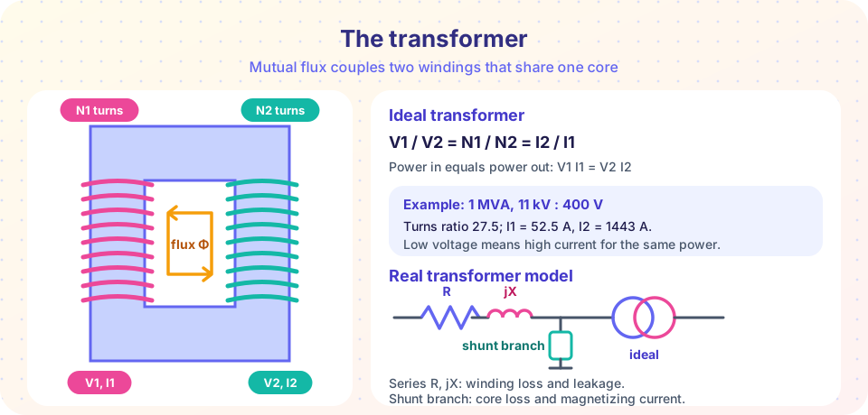
Two windings of N1 and N2 turns are wound on a common iron core. An alternating flux Φ in the core induces the same volts per turn in each winding, so
V1 / V2 = N1 / N2 = a
An ideal transformer has no losses and needs no magnetizing current, so power in equals power out, V1 I1 = V2 I2, and therefore
I1 / I2 = N2 / N1 = 1 / a
Voltage goes up, current goes down: this is the trade at the heart of transmission. A distribution transformer rated 1 MVA, 11 kV / 400 V has a ratio of 27.5. Its primary rated current is 1,000,000 / (√3 × 11000) = 52.5 A and its secondary rated current is 1,000,000 / (√3 × 400) = 1443 A.
Reflecting impedance
A load ZL on the secondary looks like a different impedance from the primary side. Since V1 = a V2 and I1 = I2 / a,
Z' = V1 / I1 = a² × ZL
An impedance is "referred" to the primary side by multiplying by a², and to the secondary by dividing by a². This lets you draw the whole system as one circuit at one voltage level, an idea that chapter 4 develops into the per-unit system.
The equivalent circuit
A real transformer has imperfections, each represented by a circuit element:
- Winding resistance
R1,R2: copper lossI²R. - Leakage reactance
X1,X2: flux that does not link both windings. - Core loss resistance
Rc(shunt): hysteresis and eddy-current loss, which depend on voltage, not on load. - Magnetizing reactance
Xm(shunt): the small current that builds the flux.
Because the shunt branch carries only about 1 to 2% of rated current, the common approximate model moves it to the primary terminals and combines the series elements, referred to one side:
Req = R1 + a² R2, Xeq = X1 + a² X2
Voltage regulation and efficiency
Worked example. A single-phase 100 kVA, 2400/240 V transformer has Req = 1.2 Ω and Xeq = 2.4 Ω referred to the high-voltage side, and a core loss of 600 W. It delivers rated current to a load at 0.8 power factor lagging, at rated secondary voltage.
- Referred secondary voltage
V2' = 2400 Vat 0°. Rated primary currentI = 100,000 / 2400 = 41.67 A, at−36.9°, which is33.33 − j25.0 A. - Series drop
(1.2 + j2.4) × (33.33 − j25.0) = 100 + j50 V. V1 = 2400 + 100 + j50 = 2500 + j50 V, so|V1| = 2500.5 V.- Regulation
= (2500.5 − 2400) / 2400 = 4.19%. (This is the rise needed at the input to hold rated voltage on the output.) - Copper loss
I² Req = 41.67² × 1.2 = 2083 W. Output power100,000 × 0.8 = 80,000 W. - Efficiency
= 80,000 / (80,000 + 2083 + 600) = 96.8%.
Efficiency peaks when copper loss equals core loss. Utilities often design distribution transformers to be most efficient around 50 to 70% of rated load, because they spend most of their time lightly loaded. Large power transformers reach more than 99%.
Three-phase transformers
A three-phase transformer is three single-phase transformers, either as three separate units (a bank) or on a common three-limbed core. The windings can be connected in wye or delta on each side. The common combinations are:
- Delta-wye (
Dyn): common for step-down at the load end, and for step-up at generators. The wye side gives a neutral. The delta circulates third-harmonic currents and keeps zero-sequence currents out of the primary system (see chapter 5). - Wye-wye: simple, but harmonics and unbalanced loads need care.
- Wye-delta and delta-delta: used where the neutral is not needed on one or both sides.
Line voltage ratio for delta-wye is VLL1 / VLL2 = a_phase × (1 / √3): the √3 from the wye side combines with the turns ratio, and the connection also shifts the phase angle by 30°. When two systems are tied through a delta-wye transformer, you must account for that shift in studies and protection.
Transformers also carry tap changers: windings with extra connection points that let the operator change the ratio by a few percent in steps of about 1.25%. An on-load tap changer (OLTC) adjusts the ratio while energized, and is a main tool for controlling voltage along a feeder.
Common misconceptions
- "A transformer makes power." It transfers power. Voltage rises and current falls, but power out never exceeds power in.
- "A transformer works on DC." A steady DC current makes a steady flux, which induces no voltage. A transformer connected to DC would draw a huge current limited only by its winding resistance.
- "Efficiency is highest at full load." Because core loss is constant and copper loss grows with load squared, the maximum efficiency is where the two are equal, often below full load.
Try it
First, use the approximate equivalent circuit to compute regulation and efficiency across loads and power factors for the 100 kVA example. The plot shows how a lagging load makes the regulation worse and a leading load can make it negative.
Press Run (or Ctrl + Enter) to see the result here.
Program input · what you'd type while the program runs
Type the answers before you press Run, one per line. Each time the program reads a line (with input()), it gets the next line from this box.
Second, a turns-ratio explorer. Choose the ratio and a load, and see the secondary current, the primary current and the load impedance as the primary sees it. It uses the ideal model.
Check your understanding
Quick check · 5 questions
of 5 answered You scored / 5 · perfect!
-
1. A transformer has 2000 turns on the primary and 100 on the secondary. If the primary is at 11 kV, what is the secondary voltage?
V2 = V1 × N2 / N1 = 11000 × 100 / 2000 = 550 V. -
2. A 4 Ω load is connected to the secondary of a transformer with a = 5. What impedance does the primary see?
Z' = a² ZL = 25 × 4 = 100 Ω. -
3. Which element of the equivalent circuit represents core loss?
Core (hysteresis and eddy-current) loss is modeled by the shunt resistance Rc. -
4. A transformer has a core loss of 400 W and a full-load copper loss of 1600 W. At what fraction of full load is its efficiency greatest?
Maximum efficiency when copper loss equals core loss: x² × 1600 = 400, so x = 0.5. -
5. Why is it a problem to connect a transformer to DC?
DC produces no induced opposing voltage, so the current is limited only by the winding resistance.
Summary
V1/V2 = N1/N2 = aandI1/I2 = 1/afor an ideal transformer; power is conserved.- Impedance referred across the transformer scales with
a². - The approximate model has
Req + jXeqin series; the shunt branch carries core loss and magnetizing current. - Regulation depends on load size and power factor; efficiency peaks when copper loss equals core loss.
- Three-phase connections (Dyn, Yy, Yd) change ratio and phase angle; tap changers fine-tune voltage.
Next: Chapter 2 Review
Track your progress
Create a free account to tick off lessons and pick up where you left off on any device.
of Electric Power Systems lessons completed