


















Lesson 4 of 47 · Getting Started
Real, Reactive and Apparent Power
Understand P, Q and S, the power triangle and power factor, and learn to size capacitors for power-factor correction with worked numeric examples.
A resistor heater turns every watt it takes into heat. A motor or a transformer does something subtler: part of the current it draws builds magnetic fields and then gives that energy back, twice every cycle. That energy does no lasting work, but the wires still have to carry it. Power engineers split the total into three quantities that make this precise: real power, reactive power and apparent power.
What you will learn
- The meaning of real power
P, reactive powerQand apparent powerS. - How to compute them from voltage and current phasors (complex power).
- What power factor means and why utilities care.
- How to size a capacitor bank for power-factor correction.
Key terms
- Real power (P): the average rate of energy conversion to useful form, in watts (W).
- Reactive power (Q): the rate of energy exchange with fields, in volt-amperes reactive (var).
- Apparent power (S): voltage times current, the loading seen by wires and transformers, in volt-amperes (VA).
- Power factor (pf): the ratio
P / S = cos φ. - Lagging / leading: current lags voltage for inductive loads and leads it for capacitive loads.
Why the powers differ
Take a sinusoidal voltage v = Vm cos ωt and a current that lags it by φ: i = Im cos(ωt − φ). Multiply them and use a trigonometric identity:
p(t) = V I cos φ × (1 + cos 2ωt) + V I sin φ × sin 2ωt
(with V, I the rms values). The first term never goes negative and averages to V I cos φ: that is the real power P. The second term swings positive and negative with zero average and amplitude V I sin φ: that is the reactive power Q. During the negative parts of p(t), energy flows back from the load to the source.
The three quantities are related by the Pythagorean theorem:
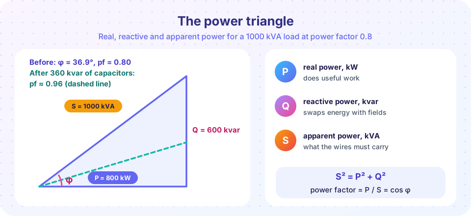
S² = P² + Q², with P = S cos φ and Q = S sin φ.
Complex power
Using phasors, define
S = V × I* (the asterisk is the complex conjugate of the current)
Then S = P + jQ. The sign convention makes Q positive for a lagging (inductive) load and negative for a leading (capacitive) load. A load "absorbs" positive Q; a capacitor bank "supplies" it by absorbing negative Q.
Example. V = 230∠0° V and I = 20∠−30° A. Then I* = 20∠+30°, so S = 230 × 20 ∠30° = 4600∠30° VA, which is 3984 W + j2300 var. The power factor is cos 30° = 0.866 lagging.
Typical sources of reactive power demand are induction motors, transformers and fluorescent ballasts. Overhead lines are inductive when heavily loaded and capacitive when lightly loaded.
Why power factor matters
Wires, transformers and generators are limited by current, and current follows S, not P. A plant that needs 800 kW at a power factor of 0.8 draws S = 1000 kVA. The same plant at power factor 1.0 would draw only 800 kVA, with 20% less current and 36% less line loss (loss goes with the current squared). Utilities therefore often charge industrial customers a penalty for a low power factor.
Power-factor correction
Because the reactive power of a capacitor has the opposite sign to an inductor's, connecting capacitors in parallel with an inductive load cancels part of Q locally, so the line carries less. The real power does not change. To move from power factor pf1 to pf2:
Qc = P × (tan φ1 − tan φ2)
Example. A 800 kW plant at pf 0.8 lagging wants pf 0.95 lagging.
tan φ1 = tan(cos⁻¹ 0.8) = 0.75.tan φ2 = tan(cos⁻¹ 0.95) = 0.3287.Qc = 800 × (0.75 − 0.3287) = 337 kvar.
The new apparent power is 800 / 0.95 = 842 kVA, down from 1000 kVA: the current falls by 16%.
Do not overcorrect. Going past pf 1 makes the load leading, which can raise the voltage and cause resonance with harmonics. Capacitor banks are often switched in steps to follow the load.
Common misconceptions
- "Reactive power is wasted." It does no net work but it is essential: it sets up the magnetic field that makes motors and transformers function. What is wasteful is carrying it over long distances.
- "A power factor of 0.9 means 90% efficiency." Power factor is about the phase angle, not about losses. A perfectly efficient inductor could have a power factor of zero.
- "Apparent powers add like real powers."
PandQadd algebraically across loads.Sadds only as complex numbers; the magnitudes do not add directly.
Try it
First, look at the instantaneous power for three loads: a resistor (φ = 0), the 0.8 power factor load (φ = 36.9°), and a pure inductor (φ = 90°). Watch how the negative lobes grow as the angle increases, while the average (the dashed line) is the real power.
Press Run (or Ctrl + Enter) to see the result here.
Program input · what you'd type while the program runs
Type the answers before you press Run, one per line. Each time the program reads a line (with input()), it gets the next line from this box.
Second, the capacitor sizing from the example, as a function of the target power factor. The plot shows how much reactive power you must supply to reach each target for the 800 kW load, and the resulting line current.
Press Run (or Ctrl + Enter) to see the result here.
Program input · what you'd type while the program runs
Type the answers before you press Run, one per line. Each time the program reads a line (with input()), it gets the next line from this box.
Third, an interactive triangle. Change the real power and the starting power factor, then add capacitors and watch the triangle shrink. It applies the formulas above.
Check your understanding
Quick check · 5 questions
of 5 answered You scored / 5 · perfect!
-
1. A load draws 3 kW and 4 kvar. What is its apparent power?
S = √(3² + 4²) = 5 kVA, and pf = 3/5 = 0.6. -
2. Which load has a lagging power factor?
Inductive loads such as motors draw current that lags the voltage. -
3. A 500 kW load at pf 0.8 lagging is corrected to pf 1.0. How many kvar of capacitors are needed?
Q = P tan φ = 500 × 0.75 = 375 kvar; correcting to unity means cancelling all of it. -
4. After adding capacitors in parallel with a load, which quantity at the load is unchanged?
Capacitors cancel reactive power but do not change the real power the load uses. -
5. V = 230∠0° V and I = 10∠+20° A. The sign of Q is:
S = V I* = 2300∠−20° VA, so Q = 2300 sin(−20°) is negative: a capacitive, leading load.
Summary
Pis useful average power,Qis energy shuttled in the fields,S = |V I*|sets the loading of equipment.S² = P² + Q²;pf = P / S = cos φ.- Inductive loads absorb
Q(lagging); capacitors supply it (leading). - Low power factor means extra current, loss and equipment size for the same real power.
- Correction:
Qc = P (tan φ1 − tan φ2); avoid overcorrecting.
Next: Chapter 1 Review
Track your progress
Create a free account to tick off lessons and pick up where you left off on any device.
of Electric Power Systems lessons completed