


















Lesson 17 of 47 · Per-Unit Analysis and Load Flow
The Per-Unit System: Bases, Change of Base and Transformers
Learn the per-unit system step by step: choosing Sbase and Vbase, deriving Ibase and Zbase, changing bases, and analyzing a multi-voltage network on one base.
Imagine measuring every distance in a country as a fraction of the distance from your house to the nearest shop. The numbers would look odd at first, but they would let you compare any two places instantly. The per-unit system does the same for voltage, current, power and impedance: it expresses each as a fraction of a chosen base value. Nearly every system study in the power industry uses it.
What you will learn
- How to choose bases and derive current and impedance bases.
- How to convert nameplate values to a common system base.
- How to solve a network that spans several voltage levels in per-unit.
- How to convert results back to amperes, volts and megawatts.
Key terms
- Base value: a reference quantity chosen for scaling; per-unit = actual / base.
- Sbase: the three-phase power base, the same everywhere in a system.
- Vbase: the line-to-line voltage base, one per voltage zone.
- Nameplate rating: the rated MVA and kV printed on equipment, which usually defines its own base.
- Change of base: converting a per-unit value from one base to another.
Defining the bases
Choose two bases independently, normally the three-phase power Sbase and the line-to-line voltage Vbase. The others follow from circuit laws:
Ibase = Sbase / (√3 × Vbase)
Zbase = Vbase² / Sbase
Then
Zpu = Zactual / Zbase, Vpu = V / Vbase, Spu = S / Sbase
Because Zbase = Vbase² / Sbase, if you use megavoltamperes and kilovolts you get ohms directly: Zbase (Ω) = Vbase(kV)² / Sbase(MVA). For Sbase = 100 MVA and Vbase = 230 kV, Zbase = 529 Ω and Ibase = 251 A. A 50 Ω line has Zpu = 0.0945.
The rule for several voltage zones
Pick one Sbase for the whole system. Pick Vbase for one zone, then set the Vbase of every other zone by the transformer ratio between them. For a transformer rated 13.8/230 kV, the zones get 13.8 kV and 230 kV. For another 230/69 kV, the next zone is 69 kV. With bases matched to the ratios, the ideal transformer disappears: voltage across the transformer is the same in per-unit on both sides, and its per-unit impedance is the same whether you refer it to the primary or the secondary.
Change of base
Equipment manufacturers give per-unit values on their own rating, for example a generator with X = 0.18 pu on 120 MVA and 13.8 kV. To use that value on the system base, convert:
Zpu,new = Zpu,old × (Vbase,old / Vbase,new)² × (Sbase,new / Sbase,old)
The voltage factor is 1 when the equipment's rated voltage matches the zone base, which is the common case. For the generator on a 100 MVA system base: 0.18 × (100 / 120) = 0.15 pu. This works because per-unit impedance is inversely proportional to the power base.
Worked example
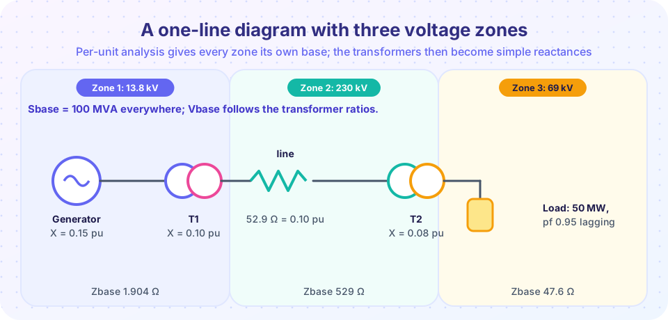
Consider the network in the picture: generator (G), step-up transformer T1, a 230 kV line, step-down transformer T2 and a load. Use Sbase = 100 MVA and zone voltage bases 13.8 kV, 230 kV and 69 kV.
Nameplates: G 120 MVA, 13.8 kV, X = 0.18 pu; T1 90 MVA, 13.8/230 kV, X = 0.09 pu; line Z = j52.9 Ω; T2 50 MVA, 230/69 kV, X = 0.04 pu; load 50 MW at power factor 0.95 lagging at 69 kV.
- Base impedances:
Zbase1 = 13.8²/100 = 1.904 Ω,Zbase2 = 230²/100 = 529 Ω,Zbase3 = 69²/100 = 47.6 Ω. - Convert to the system base:
XG = 0.18 × 100/120 = 0.15 pu,XT1 = 0.09 × 100/90 = 0.10 pu,Xline = 52.9 / 529 = 0.10 pu,XT2 = 0.04 × 100/50 = 0.08 pu. - One series circuit: total reactance
X = 0.15 + 0.10 + 0.10 + 0.08 = 0.43 pu. - Load:
S = (50 + j16.4) MVA = 0.5 + j0.164 pu. Hold the load bus atV = 1.0 pu. The current isI = S*/V* = 0.5 − j0.164 = 0.526 pu ∠−18.2°. - Generator terminal voltage:
Vg = V + jX I = 1 + j0.43 × (0.5 − j0.164) = 1.0705 + j0.215 = 1.092 pu ∠11.4°. So the generator runs at1.092 × 13.8 = 15.1 kV. - Convert back to physical units. The pu current is the same in every zone, but the base current differs:
Ibase1 = 4184 A,Ibase2 = 251 A,Ibase3 = 837 A. The actual currents are2202 A,132 Aand440 Ain the three zones. The high-voltage line carries one seventeenth of the generator current.
The generator also delivers Qg = 0.283 pu = 28.3 Mvar: the load takes 16.4 Mvar, and the series reactances of the network absorb the rest, I² X = 0.526² × 0.43 = 0.119 pu.
Three-phase quantities and delta-wye transformers
Always use three-phase power and line-to-line voltage as bases, together with the formulas above. If you instead choose single-phase bases (Sbase,1φ = Sbase/3 and line-to-neutral Vbase), the per-unit values come out identical. Phase shifts of delta-wye transformers do not appear in the per-unit magnitudes, but they appear in angles; chapter 5's fault analysis handles them explicitly.
Common misconceptions
- "You can choose any Vbase for any zone." Within a zone you choose freely only once; the others must follow the transformer ratios or the transformers do not disappear.
- "Per-unit impedance equals ohms divided by 100." It equals ohms divided by
Zbase, which depends on the voltage zone and the system power base. - "Nameplate per-unit values are already on the system base." They are on the equipment's own rating. Convert them before you add them.
Try it
First, reproduce the worked example in Python. Edit the nameplate data and the load to try other cases.
Press Run (or Ctrl + Enter) to see the result here.
Program input · what you'd type while the program runs
Type the answers before you press Run, one per line. Each time the program reads a line (with input()), it gets the next line from this box.
Second, a change-of-base calculator. Enter the per-unit value on the old base and both bases, and it returns the value on the new base. It applies the change-of-base formula directly.
Check your understanding
Quick check · 5 questions
of 5 answered You scored / 5 · perfect!
-
1. Sbase = 50 MVA and Vbase = 115 kV. What is Zbase?
Zbase = 115² / 50 = 13,225 / 50 = 264.5 Ω. -
2. A transformer has X = 0.08 pu on 25 MVA. What is X on a 100 MVA base (same voltage base)?
Xnew = 0.08 × 100 / 25 = 0.32 pu. -
3. In a system with a 100 MVA base and a 69 kV zone, a 24 Ω impedance in that zone is about:
Zbase = 69² / 100 = 47.6 Ω; 24 / 47.6 = 0.504 pu. -
4. How are zone voltage bases related across a transformer?
Choose bases in the ratio of the transformer's rated voltages so the ideal transformer disappears. -
5. A bus voltage of 0.92 pu on the 230 kV zone is:
0.92 × 230 kV = 211.6 kV.
Summary
Ibase = Sbase / (√3 Vbase),Zbase = Vbase² / Sbase, andXpu = X / Zbase.- One
Sbasefor the system; zoneVbasevalues follow the transformer ratios. - Change of base:
Zpu,new = Zpu,old (Vold/Vnew)² (Snew/Sold). - In per-unit, transformers become series reactances, and the same per-unit current flows in every zone.
- Convert back with the zone's own base to get amperes and kilovolts.
Track your progress
Create a free account to tick off lessons and pick up where you left off on any device.
of Electric Power Systems lessons completed