


















Lesson 20 of 47 · Per-Unit Analysis and Load Flow
Chapter 4 Review: Per-Unit Analysis and Load Flow
Review the per-unit system, change of base, the bus admittance matrix, bus types and Newton-Raphson load flow with a poster, recap table, solver and ten-question quiz.
Chapter 4 gave you the working method of power-system analysis: scale everything into per-unit, describe the network with Ybus, classify the buses and solve for the voltages. Every study you will meet in the rest of the course, from faults to stability, starts from these tools. Use this page to make sure they are solid.
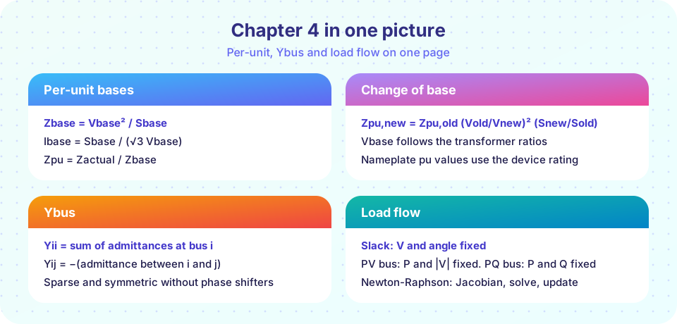
What you will review
- Base formulas, change of base and per-unit transformers.
- Building
Ybusby inspection. - Slack, PV and PQ buses and the Newton-Raphson iteration.
- DC load flow and its limits.
Recap table
| Topic | Key relations | Lesson |
|---|---|---|
| Bases | Ibase = Sbase / (√3 Vbase), Zbase = Vbase² / Sbase |
The Per-Unit System |
| Change of base | Zpu,new = Zpu,old (Vold/Vnew)² (Snew/Sold) |
The Per-Unit System |
| Zone bases | follow the transformer ratios | The Per-Unit System |
| Ybus | Yii = sum of connected admittances; Yij = −yij |
The Bus Admittance Matrix |
| Injection | Si = Vi (Σj Yij Vj)* |
The Bus Admittance Matrix |
| Bus types | slack, PV, PQ: two knowns per bus | Newton-Raphson Load Flow |
| Newton-Raphson | [ΔP; ΔQ] = J [Δδ; ΔV], repeat until the mismatch is small |
Newton-Raphson Load Flow |
| DC load flow | P = B' δ, Pij = (δi − δj) / xij |
Newton-Raphson Load Flow |
Worked review example
Two buses are joined by a 40 km, 230 kV line with z = 0.1 + j0.4 Ω/km. Bus 1 is the slack at 1.0∠0° pu. Bus 2 is a PQ load of 90 MW and 30 Mvar. Use Sbase = 100 MVA.
Zbase = 230² / 100 = 529 Ω. LineZ = 4 + j16 Ω, sozpu = 0.00756 + j0.03025 pu.y = 1 / zpu = 7.78 − j31.12 pu. The matrix isYbus = [[y, −y], [−y, y]].- The specified injection at bus 2 is
S2 = −(0.9 + j0.3) pu. With one unknown complex voltage, solveS2 = V2 × conj(Y21 V1 + Y22 V2)iteratively. - The solution is
V2 = 0.9835 pu ∠−1.45°, which is226.2 kV. - The line current is
0.965 pu, or0.965 × 251 A = 242 A. - The slack bus supplies
0.907 + j0.328 pu, so the loss is0.0070 + j0.0281 pu = 0.70 MW + 2.81 Mvar.
The reactive loss (2.81 Mvar) is four times the real loss (0.70 MW) because the line reactance is four times its resistance. This is a typical transmission-line feature that matters for voltage control in chapter 6.
Common misconceptions
- "Per-unit values of different equipment can be added directly." Only after converting them to the same system base.
- "Ybus changes when the load changes." Loads at PQ buses enter as power injections, not as part of Ybus (unless modeled as constant impedance).
- "If the iteration converges, the solution is acceptable." Check the result: voltages should be within limits (typically 0.95 to 1.05 pu), no line should be overloaded, and generator reactive powers should be within their capability.
Try it
First, a two-bus solver that reproduces the worked example. Change the line length or the load, and watch the voltage and the losses respond.
Press Run (or Ctrl + Enter) to see the result here.
Program input · what you'd type while the program runs
Type the answers before you press Run, one per line. Each time the program reads a line (with input()), it gets the next line from this box.
Second, flash cards for the formulas of the chapter. Flip each card and be honest with yourself.
Check your understanding
Quick check · 10 questions
of 10 answered You scored / 10 · perfect!
-
1. Sbase = 200 MVA and Vbase = 138 kV. What is Zbase?
Zbase = 138² / 200 = 19,044 / 200 = 95.2 Ω. -
2. A transformer has X = 0.12 pu on a 60 MVA base. Its reactance on a 100 MVA base (same voltage) is:
Xnew = 0.12 × 100 / 60 = 0.20 pu. -
3. Bus 2 connects to bus 1 through y = 3 − j9 and to bus 3 through y = 1 − j3. What is Y22?
The diagonal entry is the sum of the connected admittances: (3 − j9) + (1 − j3) = 4 − j12. -
4. A 0.5 pu current flows in the 230 kV zone. What is the current in per-unit in the adjacent 13.8 kV zone of the same system, with matched bases?
With matched bases, the per-unit current is the same on both sides of an ideal transformer. -
5. A network has 1 slack, 3 PV and 6 PQ buses. How many unknowns does Newton-Raphson solve for?
Angles at the 9 non-slack buses plus magnitudes at 6 PQ buses give 15. -
6. Which quantity does the DC load flow NOT compute?
The DC approximation fixes |V| = 1 and neglects Q, so it gives only angles and real power. -
7. What makes Newton-Raphson attractive for load flow?
Quadratic convergence gives accurate results in typically 3 to 6 iterations. -
8. Which bus voltage would an operator most likely flag as abnormal?
Normal operation keeps voltages within a few percent of 1.0 pu; 0.85 is a severe undervoltage. -
9. A generator that holds its terminal voltage at 1.03 pu and delivers 200 MW is modeled as a:
P and |V| are specified, so it is a PV bus. -
10. Why does the slack bus supply the losses?
Because the total loss is not known until the solution is found, the slack bus absorbs the difference.
Summary
- Per-unit scaling removes voltage-level bookkeeping:
Zbase = Vbase² / Sbase, change of base by(Vold/Vnew)² (Snew/Sold). Ybusis built by inspection, sparse and symmetric; injections come fromSi = Vi (Ybus V)i*.- Load flow treats buses as slack, PV or PQ and solves the nonlinear equations by Newton-Raphson.
- DC load flow is a fast linear screening tool for angles and real-power flows only.
- Chapter 5 turns to what happens when something goes wrong: short circuits, symmetrical components and protection.
Track your progress
Create a free account to tick off lessons and pick up where you left off on any device.
of Electric Power Systems lessons completed