


















Lesson 24 of 47 · Faults and Protection
Relays, breakers and coordination
Learn how overcurrent, distance and differential relays detect faults, how circuit breakers interrupt them, and how to set inverse-time relays so they coordinate.
You now know how large a fault current is. Protection is the machinery that acts on it: instrument transformers shrink currents and voltages to safe values, relays decide whether a fault is inside their zone, and circuit breakers open the circuit. The most interesting problem is not detection but coordination: when ten relays all see the same fault, only the nearest should trip first, and the others must wait in case it fails.
This lesson explains the three main relay principles, how a breaker interrupts a current that wants to keep flowing, and how to choose time settings so that relays take turns.
What you will learn
- Describe the roles of current and voltage transformers, relays and breakers in a protection chain.
- Compute the operating time of an IEC inverse-time overcurrent relay.
- Coordinate two or more relays with a coordination time interval.
- Explain distance and differential protection and when each is used.
Key terms
CT and VT: current and voltage transformers that scale primary quantities to about 1 or 5 A and 110 V for relays.
Pickup: the current above which an overcurrent relay starts to operate.
TMS (time multiplier setting): a factor that shifts a relay's time-current curve up or down.
CTI (coordination time interval): the minimum time gap between a downstream and an upstream relay, typically 0.3 to 0.5 s.
Differential protection: protection based on comparing the currents entering and leaving a zone.
The protection chain
A fault is cleared by a chain of five steps: the CT measures the current, the relay compares it with its setting, the relay closes a trip contact, the trip coil releases the circuit breaker, and the breaker's contacts separate and extinguish the arc. Total clearing time is relay time plus breaker time. A modern transmission breaker needs two to three cycles (about 40 to 60 ms at 50 Hz) and a fast relay one to two cycles, which is why fault clearing in a few cycles is a realistic target.
Interrupting a current is harder than it looks. Pull two contacts apart while a current flows and an arc forms; the arc is conductive plasma and keeps the current going. An AC breaker takes advantage of the current zero that occurs twice per cycle: it cools or blows out the arc so that when the current reaches zero it cannot restart. Vacuum breakers (used up to about 38 kV) rely on the lack of ionizable gas; SF6 breakers at higher voltages use a gas with excellent arc-quenching properties (it is also a powerful greenhouse gas, so SF6-free designs are replacing it); older oil and air-blast breakers have largely given way to these two. The interrupting rating (in kA) must exceed the maximum symmetrical fault current at the breaker's location, as computed in the previous lesson.
Overcurrent protection
The simplest relay trips when current exceeds a pickup level. Two kinds exist: an instantaneous element (device number 50) that trips immediately above a high setting, and a time-overcurrent element (51) whose operating time falls as current grows. The standard IEC 60255 characteristic is
t = TMS × k / ((I / Is)^α − 1)
with Is the pickup current, and (k, α) equal to (0.14, 0.02) for standard inverse, (13.5, 1) for very inverse and (80, 2) for extremely inverse. The curve gets steeper from standard to extremely inverse, which helps coordinate with fuses (very and extremely inverse curves resemble fuse behavior).
Choosing the pickup is a trade-off. It must be above the maximum load current plus a margin (a common rule is 1.25 to 1.5 times the maximum load) and below the minimum fault current at the end of the protected line, so the relay still sees a fault there. Ground-fault elements (50N/51N) measure the residual current 3·I0 and can be set much more sensitively because load currents are balanced and produce no zero sequence. Adding direction (67) lets an overcurrent relay respond only to faults on one side, which is needed on rings and parallel feeders.
Coordination
On a radial feeder, fault current flows through every relay between the source and the fault. All of them pick up. For selectivity the relay closest to the fault must operate first and the others must give it time. The method is:
- Set the most remote relay (furthest from the source) with the minimum TMS.
- For each relay upstream, choose a TMS so that, at the maximum fault current through the downstream relay, its operating time exceeds the downstream relay's time by the CTI. The CTI covers the breaker opening time, relay overshoot and tolerance, plus a margin: 0.3 to 0.5 s for electromechanical relays, 0.2 to 0.3 s for digital ones.
- Check the pair at other fault levels: the curves must not cross anywhere in the range of possible currents.
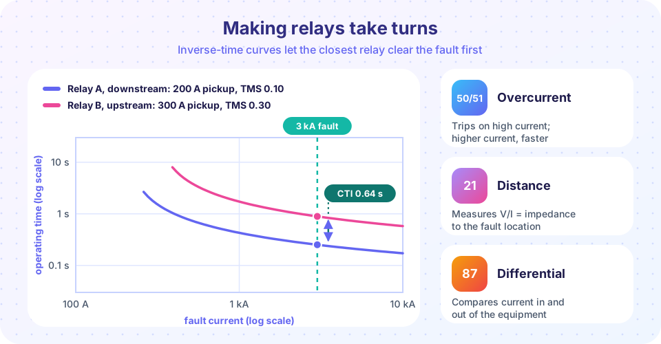
In the figure, relay A (downstream, 200 A pickup, TMS 0.10) takes 0.25 s at 3 kA and relay B (upstream, 300 A, TMS 0.30) takes 0.89 s, a margin of 0.64 s, comfortably above the CTI.
Distance protection
Overcurrent relays lose sensitivity when the source strength varies, because the fault current at a given point changes. A distance relay (device 21) measures voltage and current and computes the apparent impedance Z = V/I. For a fault on a line this impedance is proportional to the distance from the relay, because the line's impedance per kilometer is nearly constant, whatever the source. The relay trips when the measured impedance falls inside a set boundary, usually a circle on the R-X plane (a mho characteristic) or a polygon.
Distance relays are set in zones:
- Zone 1 covers about 80 to 85 % of the protected line and trips instantly. It deliberately stops short of the far end because errors in the line data and the measurement could otherwise make it reach into the next line.
- Zone 2 covers the whole line plus about half of the shortest adjacent line (roughly 120 % of the line) with a delay of about 0.3 to 0.5 s, so that the adjacent relays clear their own faults first. It protects the last 15 to 20 % of the line, which zone 1 misses.
- Zone 3 extends further as remote backup with a longer delay (around a second).
Because zone 2 only trips after a delay, faults near the end of a line would be cleared slowly. Utilities therefore link the relays at both ends by a communication channel in a pilot scheme (permissive or blocking), which allows instantaneous tripping along the entire line.
Differential protection
The most selective principle is Kirchhoff's current law applied to the whole zone: the currents entering a transformer, bus or generator must equal the currents leaving. A differential relay (87) sums the CT secondary currents; if the sum is not zero something has gone wrong inside the zone. It needs no coordination with other relays and is fast, so it is the standard protection for transformers, buses, generators and important cables.
Practical relays use a percentage (biased) characteristic. The operating current is Iop = |I1 + I2| (with currents defined into the zone) and the restraint is Ires = (|I1| + |I2|)/2. The relay trips when Iop > Imin + slope × Ires, typically with Imin ≈ 0.2 pu and a slope between 25 % and 50 %. Without a restraint, an external fault would cause a false trip whenever the two CTs saturate unequally. Transformer differential relays add second-harmonic restraint to avoid tripping on the inrush current when the transformer is energized, and compensate for the phase shift and ratio of the transformer.
Common misconceptions
"The relay is the circuit breaker." The relay only decides; the breaker acts. Both can fail, which is why backup and breaker-failure schemes exist.
"Set the pickup as low as possible for sensitivity." A pickup below the load current causes trips under normal operation. The setting lies between maximum load and minimum fault.
"Zone 1 should cover 100 % of the line." Measurement and data errors would make it overreach into the next line. Use 80 to 85 % and let zone 2 and pilot schemes cover the rest.
Try it
The first example coordinates three overcurrent relays on a radial feeder with IEC standard-inverse curves. For each pair it chooses the smallest TMS (in steps of 0.025) that gives a CTI of 0.4 s at the maximum fault current seen by the downstream relay.
Press Run (or Ctrl + Enter) to see the result here.
Program input · what you'd type while the program runs
Type the answers before you press Run, one per line. Each time the program reads a line (with input()), it gets the next line from this box.
The second example is a curve explorer. Choose the characteristic (standard, very or extremely inverse), change the TMS and the fault current, and read the operating time. It draws the IEC formula on a log-log plot.
The third example shows percentage differential protection. It checks three situations against the restraint characteristic: normal load flow, an external fault with unequal CT errors and an internal fault.
Press Run (or Ctrl + Enter) to see the result here.
Program input · what you'd type while the program runs
Type the answers before you press Run, one per line. Each time the program reads a line (with input()), it gets the next line from this box.
Check your understanding
Quick check · 5 questions
of 5 answered You scored / 5 · perfect!
-
1. A standard-inverse relay has Is = 200 A and TMS = 0.1. How long does it take at 2,000 A?
t = 0.1 x 0.14 / (10^0.02 - 1) = 0.014 / 0.0471 = 0.297 s. -
2. Why does zone 1 of a distance relay cover only 80 to 85 % of the line?
A zone set to 100 % could, with errors, trip for a fault on the adjacent line, destroying selectivity. -
3. What is the main purpose of the restraint in a differential relay?
Restraint raises the operating threshold in proportion to the through current, so CT errors do not look like an internal fault. -
4. What defines the coordination time interval between two relays?
CTI covers breaker time, relay overshoot and error margins; typical values are 0.2 to 0.5 s. -
5. How does an AC circuit breaker extinguish its arc?
The arc is cooled or blown out and the dielectric strength recovers faster than the voltage across the gap rises after current zero.
Summary
- A protection chain is CT/VT, relay, trip coil and breaker; clearing time is relay time plus breaker time (a few cycles in total).
- Overcurrent relays use
t = TMS·k/((I/Is)^α − 1); coordinate them with a CTI of 0.2 to 0.5 s at the maximum fault current of the downstream relay. - Distance relays measure
V/Iand use zones (80 to 85 %, 120 %, backup); pilot schemes add speed. - Differential relays compare currents in and out, with percentage restraint and, for transformers, harmonic restraint.
- Breakers interrupt at a current zero and must be rated above the maximum fault current.
Next: Chapter 5 review
Track your progress
Create a free account to tick off lessons and pick up where you left off on any device.
of Electric Power Systems lessons completed