


















Lesson 23 of 47 · Faults and Protection
Fault types and fault current calculation
Calculate three-phase, line-to-ground, line-to-line and double line-to-ground fault currents by connecting sequence networks, with a worked per-unit example and asymmetry factors.
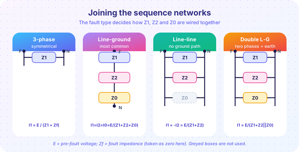
Symmetrical components give you the tool; now use it. Every fault is a simple rule about the currents and voltages at the faulted point, and that rule translates into a way of wiring the three sequence networks together. Once the networks are joined, the fault current is a one-line division: a source voltage over a total impedance.
This lesson covers the four classical faults, shows the calculation on a worked per-unit example, and explains why the first cycle of a fault current is larger than the steady value that the network equations give.
What you will learn
- Name the four fault types and the conditions that define each.
- Connect the sequence networks for each fault and write the sequence current.
- Compute phase currents in per unit and in amperes for a worked example.
- Explain why a ground fault can exceed a three-phase fault, and how DC offset raises the first peak.
Key terms
Bolted fault: a fault with zero fault impedance; it gives the maximum current.
Prefault voltage (E): the voltage at the fault point before the fault, usually taken as 1.0 per unit.
Thevenin impedance: the impedance seen looking into the network at the fault point, one for each sequence.
Effectively grounded: a system where X0/X1 ≤ 3 and R0/X1 ≤ 1, so a ground fault does not raise the healthy phase voltages much.
DC offset: the decaying direct component that makes the first cycles of a fault current asymmetrical.
The four faults
| Fault | Defining conditions (phase a reference) | Network connection |
|---|---|---|
| Three-phase (LLL) | Va = Vb = Vc (all shorted) |
Positive network only (balanced) |
| Single line-to-ground (SLG) | Va = Zf·Ia, Ib = Ic = 0 |
Positive, negative and zero in series, with 3Zf |
| Line-to-line (LL, b to c) | Ia = 0, Ib = −Ic, Vb − Vc = Zf·Ib |
Positive and negative in parallel (no zero) |
| Double line-to-ground (LLG, b and c) | Ia = 0, Vb = Vc = Zf·(Ib + Ic) |
Positive, negative and zero in parallel |
Each network is replaced by its Thevenin equivalent at the fault bus: voltage E in the positive network only, plus Z1, Z2 and Z0. Then:
LLL:  I1 = E / (Z1 + Zf),  I2 = I0 = 0
SLG:  I1 = I2 = I0 = E / (Z1 + Z2 + Z0 + 3Zf)          Ia = 3·I1
LL:   I1 = −I2 = E / (Z1 + Z2 + Zf),  I0 = 0           Ib = −Ic = −j√3·I1
LLG:  I1 = E / (Z1 + Z2·(Z0 + 3Zf)/(Z2 + Z0 + 3Zf)),
      I2 = −I1·(Z0 + 3Zf)/(Z2 + Z0 + 3Zf),   I0 = −I1·Z2/(Z2 + Z0 + 3Zf)
Finally convert the sequence currents back to phase currents with Ia = I0 + I1 + I2, Ib = I0 + a²·I1 + a·I2, Ic = I0 + a·I1 + a²·I2. The current in the ground for SLG and LLG is 3·I0.
The procedure
- Choose a common base and convert all impedances to per unit (see the per-unit lesson in the earlier chapters).
- Reduce each sequence network to a Thevenin impedance
Z1,Z2,Z0at the fault bus. Remember which transformer connections block zero sequence current. - Join the three impedances according to the fault type and compute
I1(andI2,I0). - Convert to phase currents, multiply by the base current
Ibase = Sbase/(√3·Vbase)to get amperes. - If you need bus voltages, subtract the sequence drops:
V1 = E − Z1·I1,V2 = −Z2·I2,V0 = −Z0·I0at the fault bus.
A worked example
A 230 kV bus has Thevenin sequence impedances (on 100 MVA) of Z1 = Z2 = j0.10 pu and Z0 = j0.05 pu, as it would near a solidly grounded transformer neutral. The base current is 100 MVA / (√3 × 230 kV) = 251 A. With a bolted fault (Zf = 0) and E = 1.0 pu:
- LLL:
I1 = 1/0.10 = 10 pu, soI = 10 × 251 = 2,510 A. - SLG:
I1 = 1/(0.10 + 0.10 + 0.05) = 4 pu, soIa = 3 × 4 = 12 pu = 3,012 A. - LL:
I1 = 1/0.20 = 5 pu,Ib = √3 × 5 = 8.66 pu = 2,174 A(always 0.866 of the three-phase value). - LLG:
Z2‖Z0 = 0.0333,I1 = 1/(0.10 + 0.0333) = 7.5 pu; the ground current is3·I0 = 15 pu,3,765 A.
Notice the surprise: the single line-to-ground fault is larger than the three-phase fault, because Z0 is smaller than Z1. Ground faults exceed three-phase faults on buses close to solidly grounded transformers; elsewhere (where Z0 > Z1) the three-phase fault is the largest. Breakers must be rated for whichever is greater, and the same fact tells you which fault type to use for relay setting.
The ratio of the SLG to the three-phase current is 3·Z1 / (2·Z1 + Z0) when Z1 = Z2; it equals 1 when Z0 = Z1. Quick check: with Z0 = Z1 all three sequence networks are identical, so a line-to-ground fault is as severe as a three-phase fault.
Voltages and grounding
At the fault point of an SLG fault, phase a collapses while phases b and c rise when Z0 is large. Solving the sequence equations gives the healthy phase voltages. For Z1 = Z2 and Z0 = 3·Z1 (the limit of effective grounding) the sequence voltages at the fault are V1 = 0.8, V2 = −0.2 and V0 = −0.6, and the healthy phases rise to about 1.25 pu (72 % of the line-to-line voltage); in an ungrounded system Z0 is the capacitive reactance of the lines (very large), the fault current is tiny and the healthy phases rise to line-to-line voltage, √3 times normal. That is why insulation in ungrounded or resonant-grounded systems is rated higher, and why high-voltage transmission is always effectively grounded: this keeps equipment cheaper.
Asymmetry: the first cycle
The network equations give the symmetrical rms current. But the current in an inductive circuit cannot change instantly, so when a fault occurs at an unlucky point on the voltage wave, the current has a decaying DC component that adds to the AC wave:
i(t) = √2·I·[ sin(ωt + α − φ) − sin(α − φ)·e^(−t/τ) ], τ = X / (ω·R)
The worst case gives a first peak of about √2·I·(1 + e^(−π/(X/R))). IEC 60909 uses a factor κ = 1.02 + 0.98·e^(−3R/X) such that the peak current is ip = κ·√2·I''k. For X/R = 15, κ = 1.82, so the first peak is 2.58 × I''k (rms). Breakers have a close-and-latch (making) rating and the bus bar a mechanical withstand rating that must cover this peak; the interrupting rating applies to the rms value at the moment the contacts part, when the DC part has partly decayed.
Common misconceptions
"A three-phase fault is always the worst." It is the largest only where Z0 ≥ Z1. Near solidly grounded transformers a ground fault can be larger.
"Fault current is limited by the load." The load hardly matters: fault current is set by the source and network impedance. Prefault loading is usually ignored or added as a small correction.
"Ungrounded systems are safe from ground faults." The current is small, but the healthy phase voltages rise to √3 and a persistent fault can start a second fault.
Try it
The first example is a general fault calculator. It takes Z1, Z2, Z0 and Zf and returns phase currents for all four faults, using the formulas above and complex arithmetic. The numbers are the worked example from this lesson.
Press Run (or Ctrl + Enter) to see the result here.
Program input · what you'd type while the program runs
Type the answers before you press Run, one per line. Each time the program reads a line (with input()), it gets the next line from this box.
The second example shows the effect of the zero-sequence impedance. Move Z0/Z1 and watch the ratio of the line-to-ground current to the three-phase current, 3/(2 + Z0/Z1).
The third example evaluates the asymmetry. It simulates the fault current of a series R-L circuit for the worst switching angle, compares the first peak with the IEC factor κ, and prints the symmetrical rms current for reference. All values are per unit.
Press Run (or Ctrl + Enter) to see the result here.
Program input · what you'd type while the program runs
Type the answers before you press Run, one per line. Each time the program reads a line (with input()), it gets the next line from this box.
Check your understanding
Quick check · 5 questions
of 5 answered You scored / 5 · perfect!
-
1. Which fault involves only the positive sequence network?
A balanced three-phase fault produces no negative or zero sequence currents. -
2. At a bus with Z1 = Z2 = j0.20 pu and Z0 = j0.10 pu, what is the SLG fault current in per unit (bolted, E = 1)?
I1 = 1/(0.2 + 0.2 + 0.1) = 2 pu, so Ia = 3 x 2 = 6 pu. -
3. How does a bolted line-to-line fault current compare with the three-phase fault current (Z1 = Z2)?
Ib = sqrt(3)/(2 Z1) versus 1/Z1 for three-phase, which is 0.866 of it. -
4. In an ungrounded system a line-to-ground fault raises the healthy phase voltages to about
With no ground return path the neutral shifts, so the sound phases operate at line-to-line voltage relative to earth. -
5. Why does the first peak of the fault current exceed sqrt(2) times the symmetrical rms value?
The inductive circuit cannot change current instantly, so a DC component appears and decays with time constant L/R.
Summary
- Three-phase faults use the positive network alone; SLG joins all three networks in series; LL joins positive and negative in parallel; LLG joins all three in parallel.
- Compute
I1first, then the phase currents;Ibase = Sbase/(√3·Vbase)converts per unit to amperes. - Ground faults can exceed three-phase faults where
Z0 < Z1. - Grounding decides how far healthy-phase voltages rise during a ground fault.
- DC offset makes the first peak up to about
κ·√2times the rms value, which sets making and mechanical ratings.
Track your progress
Create a free account to tick off lessons and pick up where you left off on any device.
of Electric Power Systems lessons completed