


















Lesson 29 of 47 · Stability and Control
Voltage and reactive power control
Learn why voltage follows reactive power, how the P-V nose curve limits transfer, and how generators, capacitors, tap changers, SVCs and STATCOMs keep voltage in range.
Frequency is one number for the whole grid. Voltage is the opposite: it differs at every bus, and each bus has to be kept within a band (typically about ±5 % of nominal) by local action. The reason is physical. Active power P is tied to the angle across a line and to the frequency of the whole system, while reactive power Q flows from high voltage to low voltage and is absorbed or produced locally. A bus with too little reactive supply has low voltage, and no amount of active generation elsewhere will fix it.
This lesson shows how voltage depends on P and Q, why there is a maximum power a network can deliver, and what equipment is used to hold voltage up.
What you will learn
- Explain why voltage is controlled by reactive power and frequency by active power.
- Use the approximation
ΔV ≈ (R·P + X·Q)/Vand the P-V nose curve. - Describe the main voltage control devices and what each is good at.
- Recognize the mechanism of a voltage collapse.
Key terms
Reactive power (Q): the oscillating power that builds electric and magnetic fields; measured in var. Inductive loads absorb it, capacitors and overexcited generators supply it.
P-V curve: the receiving-end voltage as a function of delivered power.
Nose point: the maximum of the P-V curve; beyond it no solution exists.
SVC / STATCOM: power-electronic devices that supply or absorb reactive power continuously.
OLTC: on-load tap changer, which adjusts a transformer ratio under load.
Why voltage follows reactive power
Consider a sending bus of voltage Vs joined to a load bus by a line of resistance R and reactance X. When the load takes P + jQ, the voltage drop is approximately
ΔV ≈ (R·P + X·Q) / V
In transmission lines X is much larger than R (the X/R ratio is 5 to 20), so the X·Q term dominates: the voltage drop is mostly caused by reactive power. Supplying Q locally therefore raises the voltage, and absorbing Q lowers it. In distribution networks R is comparable to X and both terms matter.
Another effect appears at light load. A long, lightly loaded line behaves like a big capacitor and produces reactive power. At the open (unloaded) end of a lossless line the voltage is Vr = Vs / cos(βl), where β is about 0.001 rad/km at 50 Hz. A 400 km line has βl = 0.42 rad, so the receiving end voltage is 1/cos(0.42) = 1.095 times the sending end: a rise of about 10 %, called the Ferranti effect. Shunt reactors are used to absorb the excess.
The P-V curve and the voltage stability limit
Take a lossless line (R = 0) with reactance X, a sending voltage E held constant, and a load P + jQ. The receiving voltage satisfies
V⁴ + (2QX − E²)·V² + X²(P² + Q²) = 0
V² = [ (E² − 2QX) ± √((E² − 2QX)² − 4X²(P² + Q²)) ] / 2
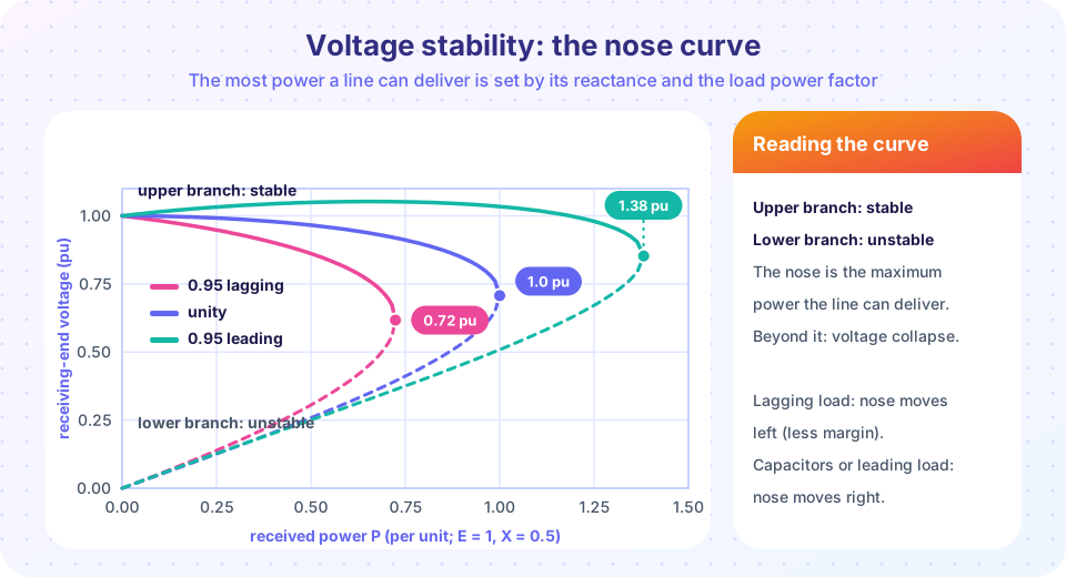
For each P there are two solutions: a high-voltage one (the normal operating point, the upper branch) and a low-voltage one. When P increases the two merge, and for larger P no real solution exists: the network simply cannot deliver that power. The merging point is the nose. At unity power factor the maximum power is Pmax = E²/(2X) at V = 0.707·E. In the figure (E = 1, X = 0.5) it is 1.0 pu, and a load with 0.95 lagging power factor reduces the limit to 0.72 pu: the reactive demand uses up part of the network's capability. A leading load, or a capacitor, raises it to 1.38 pu.
The upper branch is stable because a small increase in load lowers the voltage a little and the system settles. On the lower branch the opposite occurs and operation is unstable. The distance between the operating point and the nose, the loading margin, is the key voltage stability index.
A worked case: a load of 0.6 pu at 0.95 pf lagging (Q = 0.197) on the line above gives V = 0.806 pu, a severe sag. Adding a capacitor that supplies the 0.197 pu reactive power, so that the line carries only active power, gives V = 0.949 pu: the voltage rises by 14 % with no change to the active load.
Mechanism of a voltage collapse
Voltage collapse is a slow, positive-feedback process:
- Load grows or a line trips; reactive losses
X·I²increase and voltages fall. - Load restoration: tap changers raise the distribution voltage, thermostats and motors keep drawing power, so the demand seen by the transmission system returns toward its old value at a lower voltage, with more current.
- More current means more reactive loss in the lines, and generators near their field-current limits (over-excitation limiters) can no longer raise their emf.
- Voltage falls again and the cycle repeats until an equipment trips, induction motors stall, or voltage falls to zero over a region.
Voltage collapse typically takes tens of seconds to minutes, which gives operators and automatic schemes time to act: blocking tap changers, switching in capacitors and, as a last resort, under-voltage load shedding.
Voltage control equipment
| Equipment | How it works | Notes |
|---|---|---|
| Synchronous generator with AVR | Field current sets the terminal voltage; can supply or absorb Q within its capability curve |
Fast (cycles); the most important source of dynamic reactive reserve |
| Shunt capacitors | Supply Q proportional to V² |
Cheap, switched in steps; supply drops when voltage drops |
| Shunt reactors | Absorb Q |
Used on long lines and at light load |
| Synchronous condenser | An unloaded synchronous machine used as a variable reactive source | Also adds inertia and short-circuit strength |
| SVC | Thyristor-controlled reactor plus switched capacitors | Smooth control in cycles; Q still falls with V² at the capacitive limit |
| STATCOM | A voltage-source converter that makes a controllable current | Output current stays at its limit even at low voltage, so Q falls only with V; compact |
| OLTC transformer | Changes the turns ratio, typically ±10 % in 16 to 33 steps | Moves voltage between two sides but creates no reactive power |
Note the last line: a tap changer shifts reactive demand from one side to the other. Raising the distribution voltage by tapping increases the load current, and if the transmission side is already short of reactive power it can accelerate a collapse. That is why tap blocking is one of the standard emergency actions.
Reactive power does not travel well. Because the X·Q drop is large, Q is best produced close to where it is consumed. That is why power factor correction capacitors are installed near large motors and why distribution feeders have local capacitor banks.
Common misconceptions
"A voltage problem means too little generation." It means too little reactive support in that area; active generation elsewhere may be plentiful.
"A tap changer fixes low voltage." It fixes it for one side by pushing the problem to the other; it creates no reactive power.
"Capacitors always help." At light load they can raise voltage above limits, and at low voltage their output falls with the square of the voltage, just when it is needed.
Try it
The first example draws P-V curves for a line (E = 1, X = 0.5 pu) with three loads and prints the nose and the voltage at 0.6 pu of load, with and without a compensating capacitor. It evaluates the lossless-line formula.
Press Run (or Ctrl + Enter) to see the result here.
Program input · what you'd type while the program runs
Type the answers before you press Run, one per line. Each time the program reads a line (with input()), it gets the next line from this box.
The second example is a live voltage calculator for the same line. Move the load and the capacitor and watch the voltage; when the load exceeds the nose the message tells you that no operating point exists.
The third example evaluates the Ferranti effect on an unloaded line.
Press Run (or Ctrl + Enter) to see the result here.
Program input · what you'd type while the program runs
Type the answers before you press Run, one per line. Each time the program reads a line (with input()), it gets the next line from this box.
Check your understanding
Quick check · 5 questions
of 5 answered You scored / 5 · perfect!
-
1. In a transmission line, the voltage drop is mainly caused by
X is much larger than R, so the X x Q term dominates the voltage drop. -
2. For a lossless line with E = 1 pu and X = 0.4 pu, what is the maximum power at unity power factor?
Pmax = E^2 / (2X) = 1 / 0.8 = 1.25 pu. -
3. What does a tap-changing transformer NOT do?
It shifts the voltage and the reactive demand between sides but produces no reactive power. -
4. Why is a STATCOM better than an SVC at low voltage?
A voltage-source converter can keep delivering rated current at low voltage. -
5. On a lightly loaded long line the receiving end voltage rises. This is called the
The line's capacitance produces reactive power that raises the voltage at the open end.
Summary
- Voltage is a local quantity governed mainly by reactive power:
ΔV ≈ (R·P + X·Q)/V, withX·Qdominant in transmission. - The P-V curve has a nose; at unity power factor
Pmax = E²/(2X). Operation on the upper branch is stable, on the lower unstable; the gap to the nose is the loading margin. - Voltage collapse is a slow positive-feedback process involving load restoration and generator reactive limits.
- Control devices: generator AVR, capacitors, reactors, synchronous condensers, SVC, STATCOM and tap changers; tap changers move voltage but do not create reactive power.
- Reactive power is best supplied near the load.
Next: Chapter 6 review
Track your progress
Create a free account to tick off lessons and pick up where you left off on any device.
of Electric Power Systems lessons completed