


















Lesson 30 of 48 · Refrigeration Cycles
The vapor-compression refrigeration cycle
Trace refrigerant through compressor, condenser, expansion valve and evaporator, read the P-h diagram, and calculate COP, mass flow and the cost of a lossy compressor.
Open a refrigerator at the back and you find a black coil and a small compressor. Inside the cabinet there is a second, colder coil. Between them circulates a fluid that boils at a very low temperature. That fluid, the refrigerant, picks up heat while it boils inside the cabinet and gives it away while it condenses outside. The loop that does this is the vapor-compression cycle, used in household fridges, air conditioners, supermarket freezers and cold stores worldwide.
What you will learn
- Follow the refrigerant through the four ideal processes.
- Find the states on a P–h diagram and use
hdifferences to get COP. - Calculate mass flow, power and heat flows for a given cooling load.
- Estimate the cost of a real, non-isentropic compressor.
Key terms
Evaporator is the low-pressure heat exchanger where refrigerant boils and absorbs heat. Compressor raises the vapor pressure and temperature. Condenser is the high-pressure heat exchanger where vapor condenses. Throttling valve drops the pressure with no work and no heat, so enthalpy is constant. Saturation temperature is the boiling temperature at a given pressure.
The four ideal processes
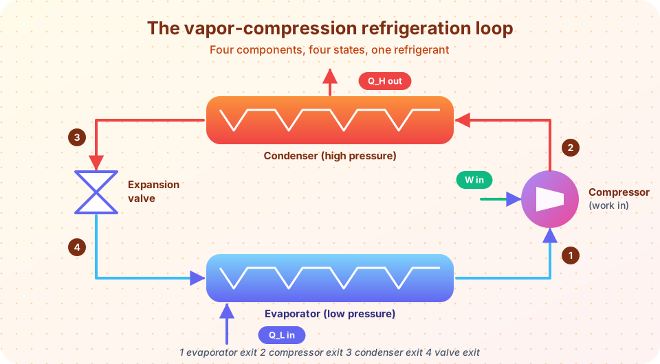
On a pressure–enthalpy (P–h) diagram the ideal cycle is a rectangle with curved sides, and heat and work show up as horizontal lengths.
- 1 → 2: isentropic compression. Saturated vapor from the evaporator enters the compressor and leaves as superheated vapor at the condenser pressure.
w_in = h₂ − h₁. - 2 → 3: constant-pressure heat rejection. The vapor cools, condenses and leaves as saturated liquid.
q_H = h₂ − h₃. - 3 → 4: throttling. The liquid passes through an expansion valve or capillary tube. The pressure falls, some liquid flashes to vapor, and the temperature drops to the evaporator temperature.
h₄ = h₃. - 4 → 1: constant-pressure heat absorption. The cold two-phase mixture boils in the evaporator, taking heat from the cold space.
q_L = h₁ − h₄.
Note a clever feature: the working temperatures are set by the pressures, not by the machine. The refrigerant boils at a low temperature because the evaporator pressure is low, and condenses at a high temperature because the condenser pressure is high.
The COP follows straight from enthalpies:
COP_R = q_L / w_in = (h₁ − h₄) / (h₂ − h₁)
Worked example with R-134a
A refrigerator uses refrigerant R-134a between 0.14 MPa (saturation temperature −18.8 °C) and 0.8 MPa (saturation temperature 31.3 °C). From standard tables (rounded): h₁ = 239.16 kJ/kg (saturated vapor at 0.14 MPa), h₂ = 275.39 kJ/kg (isentropic compression to 0.8 MPa), h₃ = h₄ = 95.47 kJ/kg (saturated liquid at 0.8 MPa).
q_L = 239.16 − 95.47 = 143.69 kJ/kg.w_in = 275.39 − 239.16 = 36.23 kJ/kg.q_H = 275.39 − 95.47 = 179.92 kJ/kg, andq_L + w_in = 179.92checks.COP_R = 143.69 / 36.23 = 3.97.
If the refrigerant mass flow is 0.05 kg/s, the cooling rate is 0.05 × 143.69 = 7.18 kW, the compressor power is 1.81 kW and the heat sent to the room is 9.00 kW.
The quality after the valve is x₄ = (95.47 − 27.08) / 212.08 = 0.32: about a third of the refrigerant flashes to vapor in the valve. That vapor does no cooling, which is one of the two reasons for a lower COP than the Carnot machine.
The reversed Carnot COP between the same saturation temperatures is 254.4 / (304.5 − 254.4) = 5.08. The vapor-compression cycle (3.97) falls short because it replaces a work-recovering expansion by a throttle and compresses dry vapor rather than a wet mixture.
Real compressors waste work
A real compressor has an isentropic efficiency η_c. The real exit enthalpy is h₂ = h₁ + (h₂s − h₁) / η_c. With η_c = 0.8 the exit enthalpy becomes 284.45 kJ/kg, the work rises to 45.29 kJ/kg, and the COP falls to 143.69 / 45.29 = 3.17. A 20 % loss in the compressor costs a 20 % drop in COP.
Real systems also include small amounts of subcooling (liquid cooled below saturation before the valve, which raises q_L) and superheating (vapor leaving the evaporator slightly above saturation, which protects the compressor from liquid). Pressure drops in the lines and heat exchangers lower the real COP further.
Why not expand in a turbine?
The Carnot cycle would extract work from the liquid as it expands. A turbine for liquid refrigerant would recover only a tiny amount of work (liquid has a small specific volume, as with the Rankine pump) and would be complex and costly, so every practical system uses a simple valve or capillary tube.
Common misconceptions
"The refrigerant gets used up." It circulates in a sealed loop; it is only lost through leaks. "Cold comes from the expansion valve." The valve lowers the pressure, and the evaporator absorbs heat by boiling. "Higher condenser pressure is harmless." It raises w_in and lowers COP, which is why dirty condenser coils waste energy.
Try it
Press Run (or Ctrl + Enter) to see the result here.
Program input · what you'd type while the program runs
Type the answers before you press Run, one per line. Each time the program reads a line (with input()), it gets the next line from this box.
Press Run (or Ctrl + Enter) to see the result here.
Program input · what you'd type while the program runs
Type the answers before you press Run, one per line. Each time the program reads a line (with input()), it gets the next line from this box.
Check your understanding
Quick check · 5 questions
of 5 answered You scored / 5 · perfect!
-
1. Which quantity stays constant across the expansion valve?
Throttling is adiabatic with no work, so h₄ = h₃. -
2. In the worked example, q_L = 143.69 kJ/kg and w_in = 36.23 kJ/kg. What is COP_R?
143.69 / 36.23 = 3.97. -
3. What determines the temperature at which the refrigerant boils in the evaporator?
At saturation, temperature and pressure are linked, so the evaporator pressure sets the boiling temperature. -
4. What happens to COP when compressor isentropic efficiency falls from 1.0 to 0.8 in the example?
w_in rises from 36.23 to 45.29 kJ/kg, so COP = 143.69 / 45.29 = 3.17. -
5. Why is a throttle used instead of a turbine?
Expanding a liquid recovers little work, so a cheap valve is the practical choice.
Summary
- Ideal cycle: isentropic compression, condensation at constant pressure, throttling at constant enthalpy, evaporation at constant pressure.
COP_R = (h₁ − h₄)/(h₂ − h₁); the example gives 3.97, below the 5.08 Carnot limit.- A throttle wastes some potential work and flashes some liquid to vapor.
- A compressor at 80 % efficiency drops the example COP to 3.17.
Track your progress
Create a free account to tick off lessons and pick up where you left off on any device.
of Engineering Thermodynamics lessons completed