


















Lesson 33 of 48 · Capacitors, Inductors and Transients
Chapter 6 Review: Capacitors, Inductors and Transients
Review capacitor and inductor laws, first-order time constants and second-order damping with a summary picture, a recap table, a script and a ten-question quiz.
This chapter introduced memory into your circuits. You met two new elements, learned that capacitor voltage and inductor current cannot jump, and followed the transient from the old steady state to the new one, smoothly (first order) or with ringing (second order). This review collects the formulas and tests your understanding with a mixed quiz.
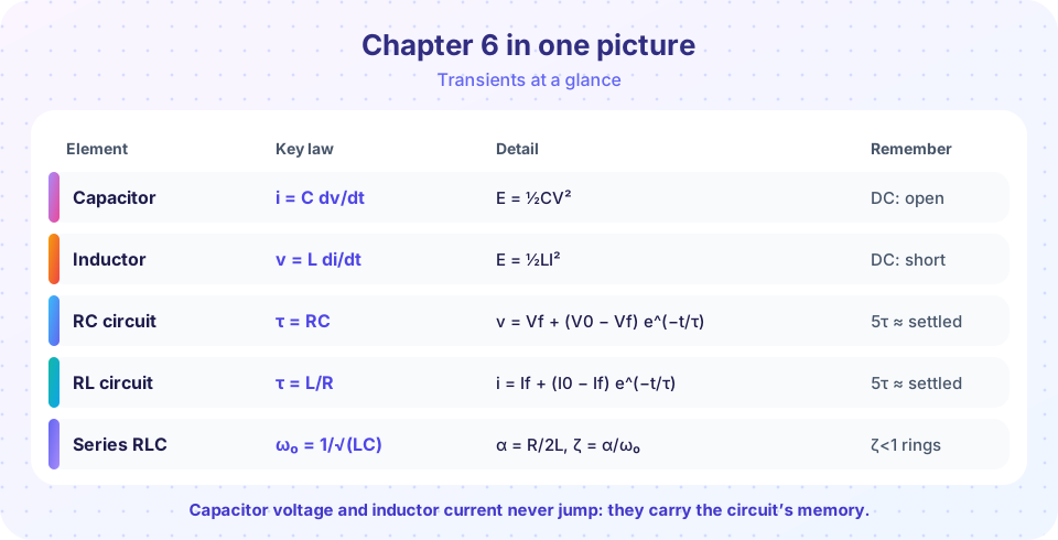
What you will learn
- A compact table of every law from the chapter.
- A routine for any first-order switching problem.
- How to recognize the damping case from component values.
Key terms
Continuity: v_C and i_L cannot jump at a switching instant.
Time constant: τ = RC or L/R, with the Thévenin resistance seen by the storage element.
Damping ratio ζ: α/ω₀, deciding under-, critical or overdamped behavior.
Recap
| Topic | Key formulas |
|---|---|
| Capacitor | i = C dv/dt, E = ½Cv², parallel: add, series: reciprocal |
| Inductor | v = L di/dt, E = ½Li², series: add, parallel: reciprocal |
| DC steady state | capacitor open circuit, inductor short circuit |
| First-order response | x(t) = x(∞) + [x(0⁺) − x(∞)] e^(−t/τ) |
| Time constants | τ = R_th C, τ = L / R_th; 63.2 % at 1τ, 99.3 % at 5τ |
| Series RLC | α = R/2L, ω₀ = 1/√(LC), ζ = α/ω₀; critical at R = 2√(L/C) |
| Underdamped | ω_d = √(ω₀² − α²), overshoot e^(−απ/ω_d) |
A routine for switching problems
- Draw the circuit for
t < 0in steady state and notev_C(0⁻),i_L(0⁻). - Draw the circuit for
t > 0. Apply continuity to get the initial values. - Find the final values with C open and L short.
- Find
Rthseen by the storage element and computeτ. - Write
x(t)with the universal formula and check it att = 0andt = ∞.
Mixed worked example
A capacitor C = 2 µF has been charged to 6 V. At t = 0 a switch connects it to a 3 kΩ resistor in parallel with a 6 kΩ resistor (both to ground).
- Initial value:
v(0⁺) = 6 V. Final value: 0 V. - Resistance seen by the capacitor:
3k ∥ 6k = 2 kΩ. τ = 2000 × 2×10⁻⁶ = 4 ms.v(t) = 6 e^(−t/4 ms). After 8 ms:6 e^(−2) = 0.81 V.- Current through the 6 kΩ at
t = 0:6 / 6000 = 1 mA. Total initial current:6 / 2000 = 3 mA.
For the second-order case, L = 10 mH, C = 1 µF gives ω₀ = 10 000 rad/s and a critical resistance of 200 Ω. Anything smaller rings, anything larger creeps.
Common misconceptions
"The initial value of a resistor voltage equals its value before the switch." Only the capacitor voltage and inductor current are continuous. Resistor voltages can jump.
"Five time constants means exactly zero." The remainder is 0.7 %, small but not zero.
"More R always damps more in every circuit." In a series RLC, α = R/2L grows with R. In a parallel RLC circuit it is the other way round: α = 1/(2RC).
Try it
This script classifies a series RLC circuit and reports its damping, ringing frequency and overshoot. Try your own component values.
Press Run (or Ctrl + Enter) to see the result here.
Program input · what you'd type while the program runs
Type the answers before you press Run, one per line. Each time the program reads a line (with input()), it gets the next line from this box.
The second program draws the chapter's key picture: time constants as tangent lines. At t = 0 the tangent to a charging curve hits the final value exactly at t = τ.
Press Run (or Ctrl + Enter) to see the result here.
Program input · what you'd type while the program runs
Type the answers before you press Run, one per line. Each time the program reads a line (with input()), it gets the next line from this box.
Check your understanding
Quick check · 8 questions
of 8 answered You scored / 8 · perfect!
-
1. A capacitor is charged to 9 V and connected across a resistor, giving τ = 5 ms. What is its voltage after 10 ms?
v = 9 e⁻² = 9 × 0.1353 = 1.22 V. -
2. An inductor carries 3 A when a switch changes the circuit. Just afterwards its current is
Inductor current is continuous, so it stays at 3 A at t = 0⁺. -
3. In DC steady state, a branch with a capacitor in series with a resistor carries
The capacitor is an open circuit in DC steady state, so the branch current is zero. -
4. A 100 Ω resistor and a 20 mH inductor have time constant
τ = L/R = 0.02 / 100 = 0.2 ms. -
5. A series RLC circuit has ζ = 0.5. It is
ζ < 1 means complex roots and ringing. -
6. Which quantity is guaranteed to be continuous at a switching instant?
Capacitor voltage and inductor current are continuous; everything else may jump. -
7. Two 12 µF capacitors in parallel and then in series with a 6 µF capacitor give
Parallel pair = 24 µF; in series with 6 µF: (24 × 6)/(24 + 6) = 4.8 µF. -
8. How long does a first-order circuit take to get within about 1 % of its final value?
e^(−t/τ) = 0.01 gives t = ln(100) τ = 4.6 τ.
Summary
- Capacitor voltage and inductor current are continuous; DC steady state makes C open and L short.
- First-order response needs three numbers: initial value, final value and
τ. - Series RLC damping is set by
ζ = α/ω₀; criticalR = 2√(L/C). - You can read
τfrom a graph: the initial tangent meets the final value att = τ.
Track your progress
Create a free account to tick off lessons and pick up where you left off on any device.
of Circuit Analysis lessons completed