


















Lesson 4 of 48 · Getting Started
Reading Circuit Schematics
Learn the standard symbols for resistors, capacitors, sources and switches, how to read wire junctions, ground and labels, and how to list a circuit as a netlist.
A schematic is the shared language of electronics. A good engineer can look at one page and see what the circuit does, the way a musician reads a score. A schematic is not a photograph: it ignores where parts physically sit and shows only how they are connected. Learn the alphabet of symbols once and you can read any circuit in this course, or in the real world.
What you will learn
- The standard symbols for the elements used in this course.
- How to read wire junctions, crossings, ground and component labels.
- How to turn a schematic into a short text description called a netlist.
- How to find the nodes of a circuit by tracing wires.
Key terms
Schematic: a diagram of components and their electrical connections.
Ground (reference node): the node chosen as 0 V, against which other voltages are measured.
Netlist: a text list of components and the nodes they connect to, used by simulators.
Polarity: which terminal of a part is + and which is −.
The symbols
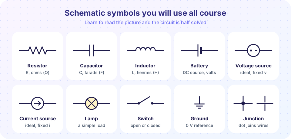
Look at the picture above. Each symbol has a standard shape (the ANSI/IEEE zigzag for a resistor is used in the US; an international (IEC) style draws it as a plain rectangle, and you will meet both):
- Resistor (R): a zigzag line. Opposes current; unit ohm.
- Capacitor (C): two parallel plates. Stores energy in an electric field (Chapter 6).
- Inductor (L): a row of loops (a coil). Stores energy in a magnetic field (Chapter 6).
- Battery: a long thin line (positive) next to a short thick line (negative). A cell is one pair of plates; a battery is several.
- Independent voltage source: a circle with + and − marks, or a sine wave inside for AC.
- Independent current source: a circle with an arrow in it.
- Lamp: a circle with a cross, representing a simple load.
- Switch: a gap with a lever, drawn open or closed.
- Ground: three shrinking horizontal bars under a vertical line.
Wires, junctions and crossings
Drawing conventions for wires cause most beginner confusion:
- A dot where wires meet means they are connected. Two wires that cross without a dot are not connected.
- Some drawers avoid ambiguity by never letting wires cross, or by using a small hop (a little arc) for a crossing. The dot rule still decides.
- A T-junction is always a connection, even without a dot, but good style adds the dot anyway.
Ideal wires have zero resistance, so every point along connected wires is the same electrical node, wherever it is in the drawing. If you redraw a circuit with a long wire shortened or bent, nothing changes electrically.
Ground
The ground symbol marks the node chosen as the voltage reference, 0 V. Every node voltage in the circuit is then measured against it. In a real mains-powered device, ground is also connected to the earth and the metal chassis for safety, but in a battery-powered analysis "ground" is just your free choice of zero. Several ground symbols in one drawing are all the same node.
Labels and polarity
Every component gets a name (R1, C2, V1) and often a value (4.7 kΩ). The name's letter tells the type: R, C, L, V (voltage source), I (current source), D (diode), Q (transistor), S or SW (switch). The name's number just distinguishes parts of one kind.
Polarity matters for sources, electrolytic capacitors and diodes. A + sign on a voltage source marks the terminal at the higher potential. For current, an arrow shows the reference direction: the direction in which we call the current positive. Choosing it arbitrarily is fine; if the solved current comes out negative, the real current flows the other way.
Finding nodes by tracing
To list the nodes in a schematic, color every wire that is connected without passing through a component: each color group is one node. For instance, a battery with R1 and R2 in a loop has three nodes: between battery + and R1; between R1 and R2; and between R2 and battery −. The three components connect those nodes in a ring.
The netlist: a schematic in text
Simulators such as SPICE do not read pictures. They read a netlist, one line per component: name, two node numbers and a value. Node 0 is ground.
V1 1 0 12     * 12 V source, + at node 1, - at node 0
R1 1 2 1k     * 1 kilohm between nodes 1 and 2
R2 2 3 2k
R3 3 0 3k
This netlist describes the series loop you will analyze in Chapter 3. SPICE uses the suffixes k (kilo), meg (mega) and m (milli), u (micro), n, p: note "m" means milli in SPICE, and 1 MΩ is written 1meg. This also teaches you something about nodes: node 2 is the junction of R1 and R2, node 3 the junction of R2 and R3.
Common misconceptions
"Crossing lines are always connected." Only a dot (or a T-junction) joins wires.
"The drawing shows the real layout." A schematic shows connections, not geometry. A wire that looks long may be a millimeter on the circuit board.
"Ground means 0 V everywhere and no current." Ground is a chosen reference; current can flow through ground connections.
Try it
The first program reads the netlist above and groups components by node, the way a simulator would begin. Edit the netlist and run it.
Press Run (or Ctrl + Enter) to see the result here.
Program input · what you'd type while the program runs
Type the answers before you press Run, one per line. Each time the program reads a line (with input()), it gets the next line from this box.
The second widget is a flashcard drill. Look at the symbol and click its name.
Check your understanding
Quick check · 5 questions
of 5 answered You scored / 5 · perfect!
-
1. Two wires cross on a schematic with no dot at the crossing. They are
Only a dot (or a T-junction) shows a connection. -
2. Which symbol is drawn as two parallel plates?
A capacitor is two plates separated by an insulator. A battery uses a long and a short plate. -
3. A netlist line reads R2 2 3 2k. This means
The format is name, node, node, value. -
4. An ideal wire joins four components at one point. How many nodes does that wire represent?
Ideal wires have no resistance, so everything connected by them is one node. -
5. What does the ground symbol mean in a battery-powered analysis?
Ground is a free choice of reference; all other voltages are measured relative to it.
Summary
- Each element has a standard symbol; learn resistor, capacitor, inductor, sources, lamp, switch, ground.
- A dot joins wires; a bare crossing does not. Wires are ideal, so connected wires form one node.
- Ground is the chosen 0 V reference.
- A netlist lists components and nodes in text, which is how simulators read circuits.
Next: Chapter 1 Review
Track your progress
Create a free account to tick off lessons and pick up where you left off on any device.
of Circuit Analysis lessons completed