


















Lesson 15 of 48 · Resistive Circuits and Ohm's Law
Series-Parallel Reduction
Solve mixed resistor networks by collapsing parallel pairs and series chains, then working back out. Includes a reduction program and the bridge circuit that will not reduce.
Real circuits mix series and parallel connections. The good news: you do not need a new law for them. You need a strategy: find the simplest series or parallel pair, replace it by its equivalent, redraw, and repeat until a single resistor is left. Then you walk backward through the same steps and recover every voltage and current.
This lesson gives you that strategy with a worked example, a program that does it automatically, and an honest look at the circuits that cannot be solved this way.
What you will learn
- A reliable procedure for reducing mixed resistor networks.
- How to work backwards to find every branch voltage and current.
- How to recognize series and parallel in a tangled drawing.
- Why a Wheatstone bridge needs a different method.
Key terms
Reduction: replacing a group of resistors by one equivalent resistor.
Equivalent circuit: a simpler circuit with the same terminal behavior.
Expansion: working back from the reduced circuit to recover internal voltages and currents.
Bridge circuit: a network of two dividers joined by a central element, which is neither series nor parallel.
The procedure
- Label nodes and resistors; mark a current direction.
- Identify a pair that is clearly parallel (same two nodes) or clearly series (the only connection at the node between them). Start from the far end of the circuit, away from the source.
- Replace it by its equivalent. Redraw.
- Repeat until one equivalent resistor Req remains across the source.
- Source current: I = Vs / Req.
- Expand: undo the steps in reverse order, applying the current-divider rule on parallel pairs and Ohm's law on series chains.
- Check with a power balance: source power = sum of resistor powers.
Worked example
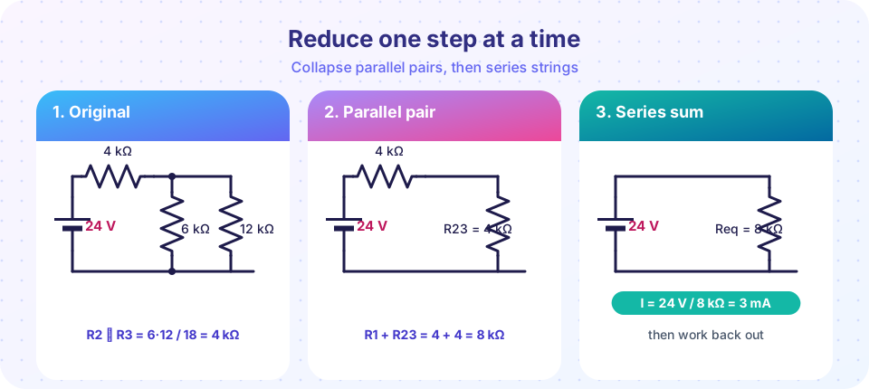
A 24 V source feeds R1 = 4 kΩ in series with the parallel pair R2 = 6 kΩ and R3 = 12 kΩ (the picture above).
- R2 ‖ R3 = 6 × 12 / (6 + 12) = 72 / 18 = 4 kΩ. Call it R23.
- R1 and R23 are in series: Req = 4 + 4 = 8 kΩ.
- Source current: I = 24 V / 8 kΩ = 3 mA. This current flows through R1.
- Expand: voltage across R1 = 3 mA × 4 kΩ = 12 V. The rest, 24 − 12 = 12 V, appears across the parallel pair (check: 3 mA × 4 kΩ = 12 V).
- Branch currents: I2 = 12 V / 6 kΩ = 2 mA, I3 = 12 V / 12 kΩ = 1 mA; they sum to 3 mA ✓.
- Power: R1 36 mW, R2 24 mW, R3 12 mW, total 72 mW = 24 V × 3 mA ✓.
A second example with more layers
Source 10 V. R1 = 100 Ω in series with a parallel group of R4 = 500 Ω and a series string R2 = 200 Ω + R3 = 300 Ω. First, R2 + R3 = 500 Ω (series). Then 500 ‖ 500 = 250 Ω. Then Req = 100 + 250 = 350 Ω. I = 10 / 350 = 28.57 mA. Voltage across R1 = 2.857 V, so the parallel group has 7.143 V; the 500 Ω R4 carries 14.29 mA, and the series string carries 14.29 mA too; the string splits the 7.143 V into 2.857 V (R2) and 4.286 V (R3).
Tips for tangled drawings
- Redraw with the same nodes in a neat layout. A node is a node however it is drawn, so slide wires to untangle.
- Same two nodes? Then the elements are parallel, no matter how the picture is arranged.
- Is anything else attached at the junction between two elements? If the junction has only those two elements, they are in series. If a third wire joins there, they are not.
- Resistors across a short circuit (a wire with no resistance between their ends) carry no current and can be removed.
- Open branches (dead ends) carry no current either.
When reduction fails: the bridge
Consider two voltage dividers (R1 over R3 on the left, R2 over R4 on the right) with a fifth resistor R5 connected between their midpoints. No pair of resistors is in series and none is in parallel, so you cannot collapse it. (There are transformations, such as the delta-wye conversion, but a systematic method is easier.) These circuits need the nodal or mesh analysis of Chapter 4.
A special case is neat: if the ratios satisfy R1/R3 = R2/R4, the two midpoints are at the same voltage, no current flows through R5, and you can ignore it. This is the balanced bridge, which is the principle behind the Wheatstone bridge used to measure an unknown resistance (and in strain gauges and many sensors).
Common misconceptions
"If two resistors look side by side in the picture, they are parallel." Parallel means the same two nodes. A drawing can mislead.
"After reduction, the voltage across Req is the voltage across every original resistor." Reduction hides internal nodes. You must expand back out to find individual values.
"Reduction works for any resistor network." Bridges and many ladder-like meshes do not reduce directly.
Try it
This program reduces a resistor network written as nested series ("S") and parallel ("P") groups, then expands it to print every resistor's voltage and current. It reproduces the worked example. Try editing the network.
Press Run (or Ctrl + Enter) to see the result here.
Program input · what you'd type while the program runs
Type the answers before you press Run, one per line. Each time the program reads a line (with input()), it gets the next line from this box.
The next program explores a Wheatstone bridge. With the bridge voltage computed from two dividers, you can see when the output is zero (balance) and how sensitive it is to a small change in one resistor.
Press Run (or Ctrl + Enter) to see the result here.
Program input · what you'd type while the program runs
Type the answers before you press Run, one per line. Each time the program reads a line (with input()), it gets the next line from this box.
Check your understanding
Quick check · 5 questions
of 5 answered You scored / 5 · perfect!
-
1. R1 = 4 kΩ in series with (6 kΩ ‖ 12 kΩ). Req is
6 ‖ 12 = 4 kΩ; add R1: 8 kΩ. -
2. Two resistors are in series only if
If a third wire attaches at the junction, the current can split there, so they are not in series. -
3. A 24 V source drives 8 kΩ equivalent. The source current is
I = 24 V / 8 kΩ = 3 mA. -
4. A bridge is balanced when
The two midpoints then have the same voltage. -
5. Why can a Wheatstone bridge generally not be solved by series-parallel reduction?
The central resistor links the two dividers, so the elements are neither in series nor in parallel.
Summary
- Reduce: replace series or parallel pairs by equivalents until one Req remains; then I = Vs/Req.
- Expand: use Ohm's law and the divider rules to recover every branch value; check the power balance.
- Parallel means the same two nodes; series means the only other connection at the junction is each other.
- Bridges do not reduce; use nodal or mesh analysis (Chapter 4). A balanced bridge has zero current in the middle branch.
Next: Chapter 3 Review
Track your progress
Create a free account to tick off lessons and pick up where you left off on any device.
of Circuit Analysis lessons completed