


















Lesson 20 of 48 · Kirchhoff's Laws and Nodal Analysis
Nodal Analysis
Solve circuits with nodal analysis: choose a reference node, write KCL with node voltages, use conductance matrices, and handle supernodes and dependent sources.
Series-parallel reduction fails on bridges and multi-source circuits, but nodal analysis never fails for a linear circuit. The idea is beautifully direct: choose one node as 0 V, give a name to the voltage of every other node, and write Kirchhoff's current law at each one using Ohm's law to express every branch current through node voltages. Out come a handful of linear equations, one per unknown node voltage.
Nodal analysis is also the algorithm behind circuit simulators such as SPICE. Learning it by hand teaches you what the computer does when you press "run".
What you will learn
- The five steps of nodal analysis.
- How to build the equations directly in conductance matrix form, G·v = i.
- What to do when a voltage source sits between two nodes (the supernode trick) and when sources are dependent.
- How to check your answers.
Key terms
Reference node: the node chosen as 0 V (ground).
Node voltage: the voltage of a node relative to the reference node.
Conductance matrix: the table of conductances that multiplies the unknown node voltages.
Supernode: two nodes joined by a voltage source, treated together in KCL.
The method
- Choose the reference node. The node with the most connections (often the bottom wire) is a good choice. Mark it as ground.
- Name the other nodes V1, V2, … These are the unknowns. If a node is tied to the reference by a voltage source, its voltage is already known, so it is not an unknown.
- Write KCL at each unknown node. Express each branch current leaving the node through Ohm's law: for a resistor from node a to node b, the current leaving a toward b is (Va − Vb)/R. Add the current-source terms.
- Solve the resulting linear system (substitution, elimination or a matrix solver).
- Check using a power balance, or recompute one branch current in two ways.
Worked example
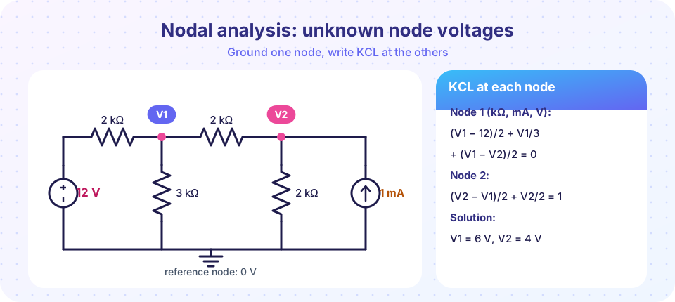
The circuit in the picture: a 12 V source feeds node 1 through 2 kΩ. Node 1 connects to ground through 3 kΩ and to node 2 through 2 kΩ. Node 2 connects to ground through 2 kΩ and receives 1 mA from a current source. Use units kΩ, mA, V.
KCL at node 1 (all currents leaving node 1 sum to zero):
(V1 − 12)/2 + V1/3 + (V1 − V2)/2 = 0
KCL at node 2 (leaving the node: through the 2 kΩ link back to node 1, through the 2 kΩ to ground; the source enters with 1 mA):
(V2 − V1)/2 + V2/2 = 1
Multiply the first by 6: 3(V1 − 12) + 2V1 + 3(V1 − V2) = 0, so 8V1 − 3V2 = 36. Multiply the second by 2: (V2 − V1) + V2 = 2, so −V1 + 2V2 = 2. Solve: from the second, V1 = 2V2 − 2. Substitute: 8(2V2 − 2) − 3V2 = 36, so 13V2 = 52, V2 = 4 V and V1 = 6 V.
Check. I through R1 = (12 − 6)/2 = 3 mA. Through R2 (3 kΩ) = 6/3 = 2 mA, through R3 (link) = (6 − 4)/2 = 1 mA; 2 + 1 = 3 ✓ (KCL at node 1). At node 2: 1 mA in from R3, plus 1 mA from the source = 2 mA, and R4 = 4/2 = 2 mA ✓. Power: the voltage source supplies 12 × 3 = 36 mW and the current source supplies 4 V × 1 mA = 4 mW, total 40 mW; the resistors absorb (12−6)²/2 + 6²/3 + 2²/2 + 4²/2 = 18 + 12 + 2 + 8 = 40 mW ✓.
Conductance matrix form
Rewrite each equation by collecting the unknowns:
- Node 1: (1/2 + 1/3 + 1/2) V1 − (1/2) V2 = 12/2
- Node 2: −(1/2) V1 + (1/2 + 1/2) V2 = 1
In matrix form G·v = i:
[ G11  -G12 ] [V1]   [ source current into node 1 ]
[ -G12  G22 ] [V2] = [ source current into node 2 ]
where G11 is the sum of all conductances connected to node 1, G22 is the sum at node 2, and G12 is the conductance directly between them (appearing with a minus sign). The right-hand side is the total current injected into each node by sources (a voltage source in series with a resistor counts as V/R). For circuits with only resistors and independent current sources the matrix is symmetric: a quick check on your bookkeeping. You can write this matrix by inspection, no KCL lines needed.
Voltage sources between nodes: the supernode
If an ideal voltage source connects two non-reference nodes, you cannot write the current through it in terms of node voltages (an ideal source can carry any current). The trick:
- Treat the source and its two nodes as a single supernode and write KCL for that whole region (currents in and out of the combined box).
- Add the constraint equation from the source: V_a − V_b = Vs.
Example. A 6 mA source feeds node 1; node 1 has 2 kΩ to ground; node 2 has 4 kΩ to ground; a 6 V source connects node 1 (+) to node 2 (−). Supernode KCL: 6 = V1/2 + V2/4. Constraint: V1 − V2 = 6. Substituting V1 = V2 + 6: 6 = (V2 + 6)/2 + V2/4, so 3 = 0.75 V2, V2 = 4 V, V1 = 10 V. Check: 10/2 + 4/4 = 5 + 1 = 6 mA ✓.
Dependent sources
Write the equations as if the dependent source were independent, then add one extra equation expressing its control variable in node voltages. If a VCCS has i = g·v_x, replace v_x by the difference of the node voltages that define it; if it is a CCCS controlled by a branch current i_x, write i_x as (Va − Vb)/R. The matrix is no longer symmetric, but the method is unchanged.
When nodal is the right choice
Nodal analysis excels when the circuit has few nodes, when there are many current sources, or when you need the voltage of a particular node, such as the output of a divider or amplifier stage. Its number of equations is (nodes − 1 − number of voltage sources connected to ground).
Common misconceptions
"The sign of each term in KCL depends on the real current direction." It depends only on your reference direction: here, all currents leaving the node, written as (V_node − V_other)/R.
"A voltage source between two nodes gives me a free equation for current." It gives a voltage constraint, V_a − V_b = Vs, but no information about its current, which is why the supernode is needed.
"Node voltages are properties of the node alone." They are measured relative to the reference node; changing the reference changes all of them by a constant, though branch voltages and currents stay the same.
Try it
This is a tiny nodal solver. It stamps each resistor into the conductance matrix automatically (the same algorithm circuit simulators use), then solves, prints node voltages and every branch current, and checks the power balance.
Press Run (or Ctrl + Enter) to see the result here.
Program input · what you'd type while the program runs
Type the answers before you press Run, one per line. Each time the program reads a line (with input()), it gets the next line from this box.
The second program uses SymPy to do the algebra exactly, including the supernode example and a general version with symbolic resistors.
Press Run (or Ctrl + Enter) to see the result here.
Program input · what you'd type while the program runs
Type the answers before you press Run, one per line. Each time the program reads a line (with input()), it gets the next line from this box.
Check your understanding
Quick check · 5 questions
of 5 answered You scored / 5 · perfect!
-
1. A circuit has 6 nodes and no voltage sources connected to the reference. How many nodal equations are needed?
One node is the reference, so there are 6 − 1 = 5 unknown node voltages. -
2. In the worked example, what is V2?
Solving 8V1 − 3V2 = 36 and −V1 + 2V2 = 2 gives V1 = 6 V and V2 = 4 V. -
3. A 6 V ideal source connects node 1 and node 2 (neither is ground). The correct approach is
The source current is unknown, so use KCL for the combined supernode plus the voltage constraint. -
4. The matrix G for a circuit of resistors and independent sources is
G12 = G21 for a network of resistors, a handy check on your equations. -
5. A dependent source in nodal analysis needs
Express the control variable (voltage or current) in terms of node voltages and substitute.
Summary
- Nodal analysis: pick a reference node, name the other node voltages, write KCL (currents leaving = 0) using Ohm's law, solve.
- Matrix form G·v = i: diagonal = sum of conductances at the node; off-diagonals = −conductance between nodes; right side = injected source currents.
- A voltage source between two non-reference nodes needs a supernode and a constraint equation.
- A dependent source adds one equation for its control variable.
- Check with power balance.
Next: Mesh Analysis
Track your progress
Create a free account to tick off lessons and pick up where you left off on any device.
of Circuit Analysis lessons completed