


















Lesson 30 of 48 · Capacitors, Inductors and Transients
Capacitors and Inductors
Learn i = C dv/dt and v = L di/dt, stored energy, DC behavior and series and parallel combinations with worked numeric examples and a live plot.
A resistor answers the question "what is the voltage right now?" with "the current times R". Capacitors and inductors answer a different question: "how fast is it changing?" They respond to change. This makes them the heart of timing circuits, filters, power supplies, oscillators and radio tuners. In this lesson you will learn their defining equations, how they store energy and how to combine several of them.
What you will learn
- The current-voltage laws of capacitors and inductors, in derivative and integral form.
- How much energy each stores.
- Series and parallel rules, and how they differ from resistors.
- The DC steady-state behavior: open circuit versus short circuit.
Key terms
Capacitance C: how much charge a capacitor holds per volt, Q = C v, measured in farads (F).
Inductance L: how much magnetic flux linkage a coil has per amp, λ = L i, measured in henries (H).
Dielectric: the insulating material between capacitor plates.
Continuity: the rule that capacitor voltage and inductor current cannot jump.
The capacitor
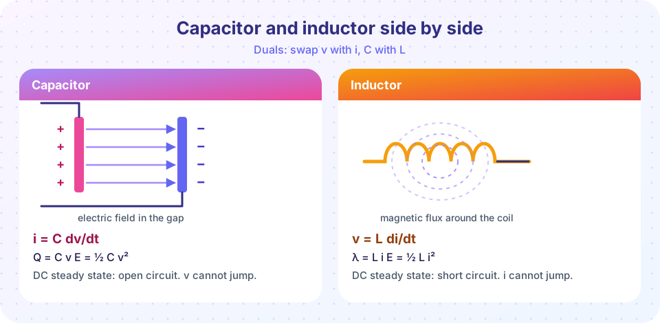
Two conducting plates separated by an insulator make a capacitor. Put charge +Q on one plate and −Q on the other and a voltage v = Q / C appears. Differentiate Q = C v with respect to time, and since current is dQ/dt:
i = C dv/dt
The current flowing into the capacitor is proportional to how quickly the voltage is rising. The integral form, v(t) = v(0) + (1/C) ∫ i dt, shows that the voltage is the accumulated charge divided by C.
Example. A 10 µF capacitor sees its voltage rise linearly from 0 to 5 V in 2 ms. The rate of change is 5 / 0.002 = 2500 V/s, so i = 10×10⁻⁶ × 2500 = 25 mA, constant during the ramp. When the voltage stops rising, dv/dt = 0 and the current drops to zero.
Energy. To raise the voltage to v the source does work E = ½ C v². For the example: ½ × 10×10⁻⁶ × 25 = 125 µJ. The energy is stored in the electric field and can be recovered.
The inductor
A coil of wire carrying current creates a magnetic field. If the current changes, the changing flux induces a voltage in the coil that opposes the change (Lenz's law). In circuit terms:
v = L di/dt
and the energy stored is E = ½ L i².
Example. A 50 mH inductor has its current ramp from 0 to 2 A in 4 ms. di/dt = 2 / 0.004 = 500 A/s, so v = 0.05 × 500 = 25 V during the ramp. The stored energy at 2 A is ½ × 0.05 × 4 = 0.1 J.
Notice the duality: capacitor i = C dv/dt, inductor v = L di/dt. Exchange v ↔ i and C ↔ L and one law turns into the other. Many results come in pairs because of this.
DC steady state
When voltages and currents settle to constants:
- Capacitor:
dv/dt = 0, soi = 0. It behaves like an open circuit, but it holds its charge. - Inductor:
di/dt = 0, sov = 0. It behaves like a short circuit, but it holds its flux.
This is how you find final values after a switch: replace capacitors by gaps, inductors by wires and solve the resulting resistive circuit.
Continuity
A jump in capacitor voltage would need infinite current (i = C dv/dt with dv/dt = ∞). A jump in inductor current would need an infinite voltage. Ideal sources can force such jumps only in contrived circuits, such as connecting two capacitors with different voltages by a perfect wire. In real circuits resistance always limits the rate. So at the instant a switch operates:
v_C(0⁺) = v_C(0⁻) and i_L(0⁺) = i_L(0⁻)
Everything else (resistor voltages, capacitor currents, inductor voltages) can jump. That is the standard starting point for transient analysis, and you will use it in the next lesson.
Combining elements
| Elements | Series | Parallel |
|---|---|---|
| Resistors | R1 + R2 |
1 / (1/R1 + 1/R2) |
| Capacitors | 1 / (1/C1 + 1/C2) |
C1 + C2 |
| Inductors | L1 + L2 |
1 / (1/L1 + 1/L2) |
Capacitors combine opposite to resistors: parallel plates add area, so capacitance adds; in series the spacing adds, so it shrinks. Inductors behave like resistors (if coils are not magnetically coupled).
Example. 10 µF and 20 µF in series give (10 × 20)/(10 + 20) = 6.667 µF; in parallel they give 30 µF. Two inductors of 8 mH and 12 mH in parallel give (8 × 12)/20 = 4.8 mH.
Common misconceptions
"A capacitor stores current." It stores charge and voltage; current only flows while the voltage changes.
"An inductor resists current." It resists changes in current. A steady current passes freely.
"Series capacitors add." Their reciprocals add, so the total is smaller than the smallest one.
Try it
The first program feeds a voltage waveform (ramp up, hold, ramp down) into a 10 µF capacitor and an inductor-current waveform into a 50 mH inductor, and plots the resulting current and voltage. Notice that nothing flows while the input is constant.
Press Run (or Ctrl + Enter) to see the result here.
Program input · what you'd type while the program runs
Type the answers before you press Run, one per line. Each time the program reads a line (with input()), it gets the next line from this box.
The second program is a calculator for combinations and energy, so you can check your own numbers.
Press Run (or Ctrl + Enter) to see the result here.
Program input · what you'd type while the program runs
Type the answers before you press Run, one per line. Each time the program reads a line (with input()), it gets the next line from this box.
Check your understanding
Quick check · 5 questions
of 5 answered You scored / 5 · perfect!
-
1. A 4 µF capacitor has its voltage rise at 1000 V/s. What current flows?
i = C dv/dt = 4×10⁻⁶ × 1000 = 4×10⁻³ A = 4 mA. -
2. A 10 mH inductor has its current rise at 200 A/s. The voltage across it is
v = L di/dt = 0.01 × 200 = 2 V. -
3. How much energy is stored in a 100 µF capacitor charged to 20 V?
E = ½ C v² = 0.5 × 100×10⁻⁶ × 400 = 0.02 J = 20 mJ. -
4. Two 6 µF capacitors in series are equivalent to
Series: 1/C = 1/6 + 1/6 = 1/3, so C = 3 µF. -
5. In DC steady state, which pair is correct?
No change means no capacitor current (open) and no inductor voltage (short).
Summary
- Capacitor:
i = C dv/dt,E = ½ C v²; inductor:v = L di/dt,E = ½ L i². - DC steady state: capacitor open, inductor short.
- Capacitor voltage and inductor current are continuous; other quantities may jump.
- Capacitors add in parallel; inductors add in series.
Next: RC and RL transients
Track your progress
Create a free account to tick off lessons and pick up where you left off on any device.
of Circuit Analysis lessons completed