


















Lesson 25 of 48 · Network Theorems
Thévenin's Theorem
Replace any linear network with one voltage source and one resistor. Find Vth and Rth step by step, check the answer, and see why it saves work.
Suppose a friend hands you a sealed box with two terminals on it. You may test it with a voltmeter, an ammeter and a few resistors, but you may not open it. Thévenin's theorem says that if the box contains only linear parts and independent sources, you can describe it completely with two numbers: a voltage and a resistance. Whatever is inside, from the outside the box behaves like a battery with a resistor in series.
What you will learn
- What the theorem states and what "equivalent" means.
- How to find
Vth(open-circuit voltage) andRth(resistance looking in). - Two other ways to find
Rth: the short-circuit current and a test source. - How to use the equivalent to study many different loads quickly.
Key terms
Terminals: the two points where the load connects, usually called a and b.
Open-circuit voltage Voc: the voltage between the terminals with nothing connected. It equals Vth.
Thévenin resistance Rth: the resistance between the terminals after all independent sources are turned off.
Short-circuit current Isc: the current that flows if the terminals are joined by a wire.
The statement
A linear two-terminal network with independent sources can be replaced, as seen from its terminals, by a voltage source Vth in series with a resistor Rth. The load sees exactly the same voltage and current as before.
Remove the load first. Everything that remains is "the network". The load can be anything, even a nonlinear device such as a diode, because the equivalent only needs the network behind the terminals to be linear.
Finding Vth
Disconnect the load and calculate the voltage across the open terminals. That voltage is Vth. Any method works: voltage dividers, nodal analysis, even superposition.
Finding Rth: three methods
Method 1: sources off. Turn off all independent sources (voltage sources become wires, current sources become gaps) and calculate the resistance between the terminals. This only works when there are no dependent sources.
Method 2: open-circuit and short-circuit. Find Voc and Isc, then Rth = Voc / Isc. This works with dependent sources too.
Method 3: test source. With independent sources off, connect a test voltage Vt across the terminals, calculate the current It it drives, and set Rth = Vt / It. This is the standard method for circuits with dependent sources.
Worked example
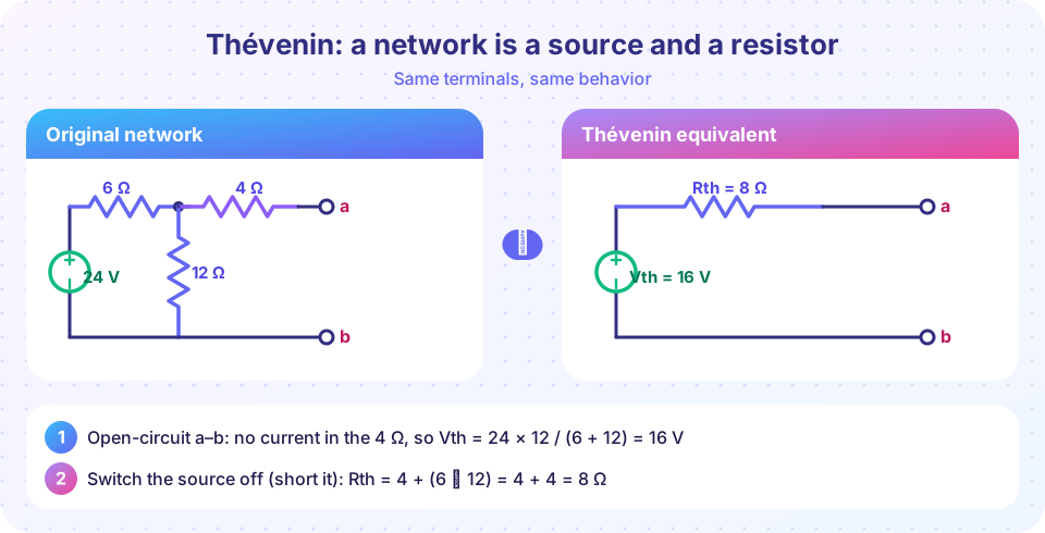
The network in the picture has a 24 V source, then 6 Ω in series, then a 12 Ω resistor from that point to ground, then another 4 Ω in series leading to terminal a. Terminal b is the ground line.
Vth. With the load removed, no current flows in the 4 Ω, so there is no voltage drop across it. Terminal a sits at the voltage across the 12 Ω:
Vth = 24 × 12 / (6 + 12) = 16 V
Rth, method 1. Short the 24 V source. Looking in from the terminals we see the 4 Ω in series with the parallel pair 6 Ω and 12 Ω:
6 ∥ 12 = (6 × 12)/(6 + 12) = 4 Ω, so Rth = 4 + 4 = 8 Ω.
Rth, method 2 as a check. Short the terminals. The 4 Ω and 12 Ω are now in parallel (3 Ω), in series with the 6 Ω, so the source sees 9 Ω. The 24 V source delivers 24/9 = 2.667 A. This current splits between 12 Ω and 4 Ω in the ratio of conductances: the 4 Ω branch gets 2.667 × 12/(12 + 4) = 2 A. So Isc = 2 A and Rth = 16 / 2 = 8 Ω. Both methods agree.
Use it. Connect an 8 Ω load to a-b. The load current is 16 / (8 + 8) = 1 A and the load voltage is 8 V. A 4 Ω load gets 16 / 12 = 1.333 A, and so on. You never need to touch the original network again.
Why it saves work
Imagine the load resistor of a power supply varies from 1 Ω to 100 Ω. Without Thévenin you would redo the nodal analysis for each value. With the equivalent, every load needs one division. Engineers also use it the other way round: a signal source has a Thévenin resistance (its output impedance), and knowing it tells you how much the signal drops when you connect a load.
Dependent sources and the test source
When a network contains a dependent source, turning the independent sources off does not make the dependent source disappear, because it still reacts to circuit variables. Use the test-source method. Suppose a 2 kΩ resistor is in series with a current-controlled voltage source 10 × Ix, where Ix is the current through the terminals. Connecting a test voltage Vt produces It, and the network equation is Vt = 2000 It + 10 It, so Rth = 2010 Ω. The key point is that the answer is still just a resistance, which could even be negative for active circuits.
Common misconceptions
"Rth is the resistance of the whole circuit." Only of what you see between the two chosen terminals, with sources off. Change the terminals and Rth changes.
"Power in the equivalent equals power in the original." Only the load power matches. The source and Rth in the equivalent dissipate different power from the real network.
"Turn the load off to find Rth." The load is removed before you start; then the independent sources are turned off. These are separate steps.
Try it
The first program checks the theorem numerically: it builds the original network with the load attached, solves it with nodal analysis for several loads, and compares with the Thévenin prediction.
Press Run (or Ctrl + Enter) to see the result here.
Program input · what you'd type while the program runs
Type the answers before you press Run, one per line. Each time the program reads a line (with input()), it gets the next line from this box.
The second demo lets you drag the load resistor and see the load voltage, current and power from the Thévenin equivalent. Notice that the voltage always sits between 0 V and 16 V.
Check your understanding
Quick check · 5 questions
of 5 answered You scored / 5 · perfect!
-
1. In the worked example, why is Vth equal to the voltage across the 12 Ω resistor?
An open circuit at a-b means zero current in the series 4 Ω, so terminal a sits at the same voltage as the top of the 12 Ω. -
2. How do you find Rth when the network contains dependent sources?
Dependent sources stay active, so turn off only the independent ones and apply a test source, or compute Voc / Isc. -
3. A network has Voc = 20 V and Isc = 5 A. What is its Thévenin resistance?
Rth = Voc / Isc = 20 / 5 = 4 Ω. -
4. With Vth = 16 V and Rth = 8 Ω, what is the current in a 24 Ω load?
I = 16 / (8 + 24) = 0.5 A. -
5. The Thévenin equivalent is valid for
Only the part being replaced must be linear; the load can be anything.
Summary
- Any linear network behind two terminals equals
Vthin series withRth. Vthis the open-circuit voltage;Rthis found with sources off, withVoc/Isc, or with a test source.- Check your
Rthby a second method whenever you can. - The load can change freely: the equivalent never needs recomputing.
Track your progress
Create a free account to tick off lessons and pick up where you left off on any device.
of Circuit Analysis lessons completed