


















Lesson 37 of 48 · AC Circuits and Phasors
AC Power: Real, Reactive and Apparent
Understand instantaneous and average AC power, the power triangle, complex power and power-factor correction with a full worked example and live plots.
In a DC circuit power is simply voltage times current. In an AC circuit the story is richer. Voltage and current both oscillate, they may be out of phase, and in some moments power flows back from the load to the source. Engineers split AC power into three related quantities: the real power that does useful work, the reactive power that shuttles in and out of fields, and the apparent power that the equipment must be built to handle. Utilities even charge industrial customers for a poor power factor, so this lesson is also about money.
What you will learn
- How instantaneous power behaves and what its average means.
- The definitions of
P,Q,Sand the power factor. - Complex power
S = V I*. - How to correct a poor power factor with a capacitor.
Key terms
Real power P: the average power, in watts (W); what heats, spins and lights.
Reactive power Q: the amplitude of the power that oscillates in and out of inductors and capacitors, in volt-amperes reactive (var).
Apparent power S: Vrms Irms, in volt-amperes (VA); the rating equipment must support.
Power factor pf: P / S = cos φ; a lagging pf means an inductive load, a leading pf a capacitive one.
Instantaneous power
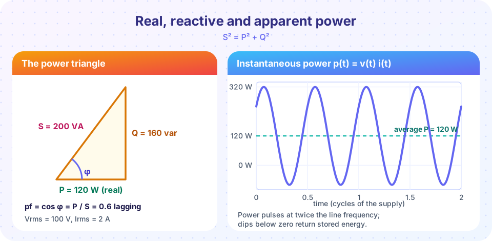
Take v(t) = √2 V cos ωt and i(t) = √2 I cos(ωt − φ) where V and I are RMS values and φ is the angle by which the current lags the voltage. The instantaneous power is p = v i. Using the product-to-sum identity:
p(t) = V I cos φ + V I cos(2ωt − φ)
It has a constant part V I cos φ and an oscillating part at twice the supply frequency. The average over a cycle is the constant part:
P = V I cos φ
This is the real power. Whenever φ ≠ 0 the oscillating part dips below zero for part of the cycle, meaning energy returns from the load's magnetic or electric fields to the source.
The three powers
- Real power:
P = V I cos φ(watts). - Reactive power:
Q = V I sin φ(var). Positive for inductive loads, negative for capacitive loads. - Apparent power:
S = V I(VA).
They form a right triangle: S² = P² + Q², pf = cos φ = P/S, tan φ = Q/P.
For a resistor, φ = 0: Q = 0, P = S. For an ideal inductor or capacitor, φ = ±90°: P = 0, all power is reactive. In terms of impedance Z = R + jX: P = I² R and Q = I² X.
Example. The R-L circuit from the previous lesson (V = 100 V RMS, I = 2 A, φ = 53.13°): S = 200 VA, P = 200 × 0.6 = 120 W, Q = 200 × 0.8 = 160 var, pf = 0.6 lagging. Check with the elements: P = I² R = 4 × 30 = 120 W and Q = I² X_L = 4 × 40 = 160 var.
Complex power
Define S = V I* where I* is the complex conjugate of the current phasor (RMS values). With V = 100 ∠ 0° and I = 2 ∠ −53.13°: I* = 2 ∠ +53.13°, so
S = 200 ∠ 53.13° = 120 + j160 VA
The real part is the real power and the imaginary part is the reactive power. This compact rule handles every case: power is conserved in the complex sense, so the complex powers of all elements in a circuit sum to the source's complex power.
Why power factor matters
The load draws P = 120 W of useful power, but the current is 2 A. At unity power factor the same 120 W at 100 V would need only 1.2 A. The extra current does no work, yet it flows through every wire, transformer and generator winding on the way, wasting I² R in line resistance and demanding bigger equipment. Utilities therefore penalize low power factors in factories full of motors, which are inductive.
Suppose the supply line has a resistance of 0.5 Ω. With 2 A the line loses 4 × 0.5 = 2 W; with 1.2 A it loses 1.44 × 0.5 = 0.72 W. Scale this to megawatts and the savings are large.
Power-factor correction
Since motors are inductive (positive Q), add a capacitor in parallel to supply negative reactive power locally. To fix the example load (P = 120 W, Q = 160 var, V = 100 V, ω = 1000 rad/s):
- Target unity pf: the capacitor must supply
Q_C = 160 var. A capacitor hasQ_C = V² ω C, soC = 160 / (10 000 × 1000) = 16 µF. The new current is120 / 100 = 1.2 AandS = 120 VA. - Target
pf = 0.95lagging instead (cheaper, avoiding over-correction): the newQ = P tan(arccos 0.95) = 120 × 0.3287 = 39.4 var, so the capacitor supplies160 − 39.4 = 120.6 varandC = 120.6 / 10⁷ = 12.1 µF.
The load itself is unchanged: it still takes 120 W. Only the current drawn from the line changes. Notice that the capacitor is placed in parallel, so the load voltage stays put.
Maximum power in AC
Maximum average power transfer needs Z_L = Z_th*: the load resistance equals the source resistance, and the load reactance is the opposite sign to the source reactance, so the reactances cancel. If the load can only be adjusted in resistance, the best choice is R_L = |Z_th|.
Common misconceptions
"Reactive power is wasted." It is not dissipated as heat in an ideal reactance; it is stored and returned each cycle. It still loads cables and generators, which is why it costs money.
"Apparent power is real power plus reactive power." They add as the sides of a right triangle, not arithmetically: S = √(P² + Q²).
"Power factor correction reduces the energy used by the load." The load's real power is unchanged; only the line current (and its losses) falls.
Try it
The first program computes P, Q, S from phasors and designs a power-factor correction capacitor for a target pf.
Press Run (or Ctrl + Enter) to see the result here.
Program input · what you'd type while the program runs
Type the answers before you press Run, one per line. Each time the program reads a line (with input()), it gets the next line from this box.
The second program plots instantaneous power for the same load. The pink area under the dashed average line shows the net energy flow; the dips below zero are energy returning to the source.
Press Run (or Ctrl + Enter) to see the result here.
Program input · what you'd type while the program runs
Type the answers before you press Run, one per line. Each time the program reads a line (with input()), it gets the next line from this box.
Check your understanding
Quick check · 6 questions
of 6 answered You scored / 6 · perfect!
-
1. A load draws 5 A at 200 V RMS with a power factor of 0.8. The real power is
S = 200 × 5 = 1000 VA, so P = S × pf = 800 W. -
2. For that load, the reactive power is
Q = √(S² − P²) = √(1000² − 800²) = 600 var. -
3. An ideal capacitor in an AC circuit consumes
Its current and voltage are 90° apart, so the average of v i is zero; it only swaps energy with the source. -
4. Where is a power-factor correction capacitor connected relative to the load?
In parallel the load voltage is unchanged and the capacitor supplies reactive power locally. -
5. Complex power is
S = V I* (RMS phasors), whose real part is P and imaginary part Q. -
6. A load has P = 300 W and Q = 400 var. The apparent power is
S = √(300² + 400²) = 500 VA.
Summary
p(t)has a constant partV I cos φand a part at twice the line frequency; the average is the real powerP.P = V I cos φ,Q = V I sin φ,S = V I,S² = P² + Q²,pf = cos φ.- Complex power
S = V I* = P + jQ. - A parallel capacitor cancels inductive reactive power, lowers the line current and the losses without changing the load's real power.
Next: Chapter 7 review
Track your progress
Create a free account to tick off lessons and pick up where you left off on any device.
of Circuit Analysis lessons completed