


















Lesson 39 of 48 · Frequency Response and Resonance
Chapter 8 Overview: Frequency Response and Resonance
See how circuits treat different frequencies differently: transfer functions, decibels, filters and resonance, with a chapter map and two live demos.
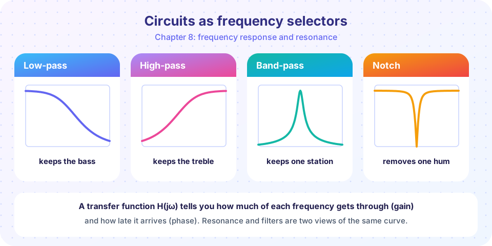
Turn the bass knob on a stereo and low notes get louder while high notes stay put. Tune a radio and one station comes through while all the others fade. Both are examples of a circuit treating some frequencies differently from others. Because capacitor and inductor impedances depend on frequency, every circuit that contains them has a frequency response: a gain and a phase shift for each frequency. This chapter shows how to describe, plot and design that behavior.
What you will learn
- What a transfer function is and what gain and phase mean.
- Why engineers use decibels and logarithmic frequency axes.
- The four basic filter types and what resonance is.
- How the lessons of this chapter fit together.
Key terms
Transfer function H(jω): the ratio of output phasor to input phasor, Vout / Vin, as a function of frequency.
Gain |H|: how much the amplitude is multiplied at a given frequency.
Decibel (dB): a logarithmic unit of ratio; for voltage gain, 20 log₁₀ |H|.
Cutoff frequency: where the gain has fallen to 0.707 of its maximum, i.e. −3 dB.
One idea: H(jω)
Feed a sinusoid Vin ∠ 0° of frequency ω into a linear circuit. In steady state the output is a sinusoid of the same frequency, Vout = H(jω) Vin. H(jω) is a complex number: its magnitude is the gain and its angle is the phase shift. Repeat for every frequency and you have the frequency response.
Example: a resistor R in series with a capacitor C, with the output taken across the capacitor. A voltage divider gives
H(jω) = [1/(jωC)] / [R + 1/(jωC)] = 1 / (1 + jωRC)
At low frequencies ωRC ≪ 1 and H ≈ 1: the signal passes. At high frequencies |H| ≈ 1/(ωRC) and falls: the capacitor shorts the output. This is a low-pass filter.
Why decibels and log axes?
Frequencies in practice span many decades (a hearing range of 20 Hz to 20 kHz covers three), and gains span many orders of magnitude. A linear axis would squash most of the interesting action into a tiny corner. On a logarithmic frequency axis each decade takes the same width, and on a decibel scale the response of cascaded stages simply adds: a 6 dB stage followed by a 14 dB stage gives 20 dB. A power change of a factor of two is about 3 dB; a voltage factor of 10 is 20 dB. Remembering a few values pays off:
| Voltage ratio | dB |
|---|---|
| 0.5 | −6.02 |
| 0.707 | −3.01 |
| 1 | 0 |
| 2 | +6.02 |
| 10 | +20 |
| 100 | +40 |
Frequency response
Four filters
Resonance
Tools
Chapter map
| Lesson | What it covers |
|---|---|
| Transfer functions and Bode plots | H(jω), magnitude in dB, phase, straight-line asymptotes |
| Filters | Low-pass, high-pass, band-pass and band-stop circuits, cutoff frequencies |
| Resonance and quality factor | Series RLC, f₀, Q, bandwidth |
| Chapter review | Mixed problems and a recap |
Common misconceptions
"A filter removes frequencies completely." Real filters attenuate gradually; at the cutoff the amplitude is still 70 % of the pass-band value.
"dB is a unit of voltage." It is a ratio of two quantities of the same kind; it needs a reference (or another signal) to mean anything.
Try it
This program tabulates the gain and phase of the RC low-pass filter at several frequencies. The cutoff frequency is 1/(2πRC) ≈ 995 Hz for R = 1.6 kΩ and C = 100 nF.
Press Run (or Ctrl + Enter) to see the result here.
Program input · what you'd type while the program runs
Type the answers before you press Run, one per line. Each time the program reads a line (with input()), it gets the next line from this box.
The second demo shows input and output waves while you sweep the frequency of the same filter. Watch the output shrink and slide to the right as the frequency rises past the cutoff.
Check your understanding
Quick check · 5 questions
of 5 answered You scored / 5 · perfect!
-
1. A transfer function H(jω) is
It is the output phasor divided by the input phasor, and it depends on frequency. -
2. A gain of 0.1 (voltage) is
20 log₁₀(0.1) = −20 dB. -
3. In the RC low-pass filter (output across C), at very high frequency the capacitor behaves like
Its impedance 1/(ωC) tends to zero, shorting the output. -
4. The cutoff frequency corresponds to a gain of
At the cutoff the amplitude gain is 1/√2 = 0.707, i.e. −3 dB. -
5. Why are cascaded stages easy to handle in decibels?
Because log(ab) = log a + log b, the dB gains of stages simply add.
Summary
H(jω) = Vout / Vinhas a magnitude (gain) and an angle (phase shift) for every frequency.- Capacitor and inductor impedances depend on frequency, so circuits act as filters.
- Decibels (
20 log₁₀ |H|) and log frequency axes make wide-ranging responses readable. - Cutoff is the −3 dB point where the gain is 0.707 of its maximum.
Track your progress
Create a free account to tick off lessons and pick up where you left off on any device.
of Circuit Analysis lessons completed