


















Lesson 13 of 48 · Resistive Circuits and Ohm's Law
Series Resistors and the Voltage Divider
Add resistors in series, find the shared current, split a voltage with the divider rule, design a divider, and see how a load changes the output.
Resistors in series are like people in a single-file queue: whatever flows through one must flow through the next. This simple fact gives us two of the most-used tools in electronics: the rule for adding series resistances, and the voltage divider, a pair of resistors that turns one voltage into a smaller one. Dividers are inside volume knobs, sensor circuits, battery monitors and the input of every oscilloscope.
What you will learn
- Why series elements share the same current and how to add their resistances.
- Kirchhoff's voltage law applied to a series loop.
- The voltage divider rule and how to design a divider.
- How a load connected to the output changes a divider.
Key terms
Series connection: elements joined end to end so that the same current flows through all of them.
Equivalent resistance (Req): one resistor that can replace the combination without changing the source current.
Voltage divider: a series chain used to produce a fraction of the input voltage at an intermediate node.
Loading: the change in a circuit's behavior caused by connecting something to its output.
The series rule
If R1, R2, …, Rn are in series, charge has no other path to take, so the same current I flows through every one. Each resistor drops a voltage V_k = I·R_k. The source voltage must equal the sum of the drops (energy per coulomb is conserved around the loop, Kirchhoff's voltage law from Chapter 4):
Vs = I·R1 + I·R2 + … + I·Rn = I·(R1 + R2 + … + Rn)
So the combination behaves like one resistor:
Req = R1 + R2 + … + Rn
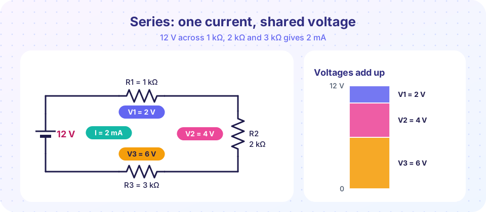
Worked example. The figure shows 12 V across 1 kΩ, 2 kΩ and 3 kΩ in series. Req = 6 kΩ. The current is I = 12 V / 6 kΩ = 2 mA. The drops are 2 V, 4 V and 6 V, which add to 12 V. Powers: 4 mW, 8 mW, 12 mW, total 24 mW = 12 V × 2 mA ✓.
Two observations are worth remembering:
- Req is always larger than any single resistor in the chain.
- The biggest resistor gets the biggest share of the voltage and the biggest share of the power.
The voltage divider rule
Take two resistors R1 and R2 in series across a source voltage Vin. The current is I = Vin / (R1 + R2). The voltage across R2 is
Vout = I · R2 = Vin · R2 / (R1 + R2)
and across R1 it is Vin · R1 / (R1 + R2). For any number of resistors, the voltage across Rk is Vin · Rk / Rtotal. In words: each resistor takes the same fraction of the voltage as its share of the total resistance.
Quick estimates. Equal resistors split the voltage equally. If R2 is nine times R1, Vout is 9/10 of Vin. If R2 is much smaller than R1, Vout is tiny.
Worked example (design). You need 3.3 V from a 5 V supply. We need R2 / (R1 + R2) = 3.3 / 5 = 0.66. Choose R2 = 3.3 kΩ; then R1 + R2 = 5 kΩ, so R1 = 1.7 kΩ. Standard values 1.8 kΩ and 3.3 kΩ give Vout = 5 × 3.3 / 5.1 = 3.24 V, within 2% of the target.
The divider is also the basis of the potentiometer (a variable resistor): the sliding contact picks off a fraction of the voltage between its two ends, which is how a volume knob works.
The loaded divider
A divider's output is only as stable as the thing connected to it. Connect a load RL across R2 and R2 effectively becomes R2 in parallel with RL, which is smaller, so Vout drops.
Worked example. Vin = 10 V, R1 = R2 = 10 kΩ. Unloaded: Vout = 5 V. Connect a load of 10 kΩ: R2 ‖ RL = 5 kΩ, so Vout = 10 × 5 / (10 + 5) = 3.33 V. Connect a 1 MΩ load instead (an oscilloscope-like input): R2 ‖ RL ≈ 9.9 kΩ and Vout = 4.98 V, barely changed.
Rule of thumb: the load should be at least ten times larger than the divider resistor it sits across (R2), or the error exceeds about 10%. When you need a stiff voltage for a real load, a divider is the wrong tool: use a regulator or an amplifier.
Sign and polarity
The voltage-divider rule gives the magnitude when the reference polarities agree with the current direction. If you define Vout with + at the node and − at ground, and the source + is at the top of the divider, the formula as written is correct with no sign flip. If you define the polarity opposite, put in a minus sign. Always draw the reference marks first.
Common misconceptions
"The voltage drops differently across each resistor because the current changes." The current is identical in all series resistors; the voltages differ because the resistances differ.
"The divider formula works unchanged with a load." The formula applies to the unloaded divider. With a load, use R2 ‖ RL in place of R2.
"Series resistors add to a value smaller than the largest." Series always adds: Req ≥ the largest.
Try it
This program solves any series string: it finds the current, every voltage drop and every power, and draws a stacked bar showing how the source voltage divides.
Press Run (or Ctrl + Enter) to see the result here.
Program input · what you'd type while the program runs
Type the answers before you press Run, one per line. Each time the program reads a line (with input()), it gets the next line from this box.
Slide the bottom resistor of a divider and watch the output change. The output voltage follows the formula, and the second slider adds a load to show loading.
The last program quantifies loading. For a 10 kΩ / 10 kΩ divider from 10 V, it prints the output for several loads.
Press Run (or Ctrl + Enter) to see the result here.
Program input · what you'd type while the program runs
Type the answers before you press Run, one per line. Each time the program reads a line (with input()), it gets the next line from this box.
Check your understanding
Quick check · 5 questions
of 5 answered You scored / 5 · perfect!
-
1. Three resistors of 100 Ω, 220 Ω and 680 Ω are in series. Req is
100 + 220 + 680 = 1,000 Ω. -
2. R1 = 2 kΩ and R2 = 6 kΩ in series across 12 V. The voltage across R2 is
Vout = 12 × 6 / (2 + 6) = 9 V. -
3. Which is true for resistors in series?
Series elements carry the same current. -
4. A divider's output falls when a load is connected because
R2 ‖ RL < R2, so its share of the voltage falls. -
5. You want a divider with Vout = Vin/4 using R2 = 1 kΩ. What is R1?
R2/(R1 + R2) = 1/4 → R1 + R2 = 4 kΩ → R1 = 3 kΩ.
Summary
- Series resistors carry the same current and add: Req = R1 + R2 + …
- Voltages divide in proportion to resistance: Vk = Vin · Rk / Rtotal.
- A divider's output drops when loaded; use RL ≥ 10 × R2 for less than about 10% error.
- Always check: the drops add to the source, and the powers add to the source power.
Track your progress
Create a free account to tick off lessons and pick up where you left off on any device.
of Circuit Analysis lessons completed