


















Lesson 43 of 48 · Frequency Response and Resonance
Chapter 8 Review: Frequency Response and Resonance
Review transfer functions, decibels, Bode plots, filters and resonance with a summary picture, a design script, a sweep plot and a ten-question mixed quiz.
Chapter 8 showed that a circuit is not just a thing that answers "what is the current?". It is a function of frequency. You learned to describe that function with a transfer function, draw it on a Bode plot, build filters from it and understand resonance as the special case where inductor and capacitor cancel. This review ties those threads together.
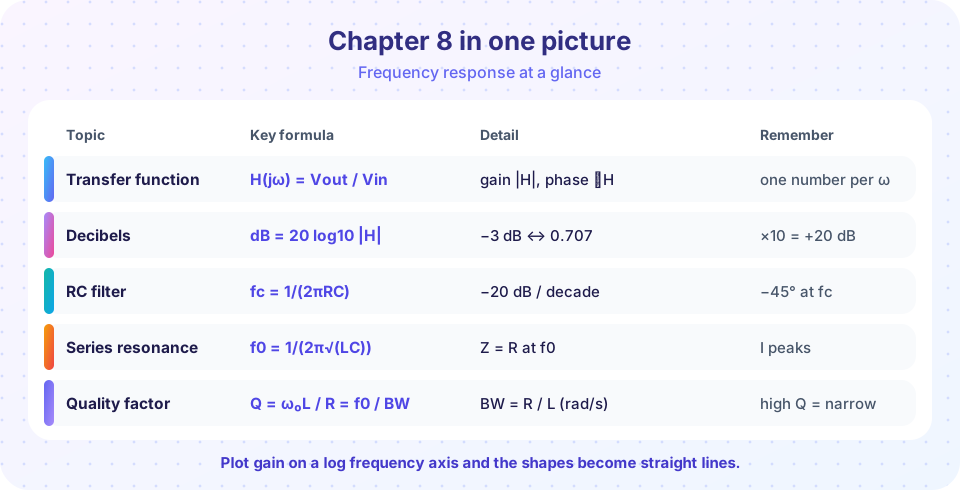
What you will learn
- A single table of formulas and rules of thumb for the chapter.
- How to combine them in a design: choosing parts for a given cutoff or resonance.
- How to check your answer with a few quick estimates.
Key terms
Transfer function: H(jω) = Vout/Vin.
Corner / cutoff: the −3 dB frequency of a first-order stage.
Resonance: ω₀ = 1/√(LC), with Q = ω₀L/R.
Bandwidth: B = f₀/Q for a resonant band-pass filter.
Recap
| Topic | Rules |
|---|---|
| Gain in decibels | dB = 20 log₁₀ (gain); ×2 ≈ +6 dB, ×10 = +20 dB, 0.707 = −3 dB |
| First-order RC | f_c = 1/(2πRC); −20 dB/decade; phase −45° at f_c |
| Low-pass / high-pass | Output across C / across R of a series RC |
| Band-pass / band-stop | Series RLC, output across R / across L + C |
| Resonance | f₀ = 1/(2π√(LC)), Z = R at f₀ |
| Quality factor | Q = ω₀L/R = f₀/B; V_L = V_C = Q Vs at resonance |
| Cascading | Gains in dB add; poles add −20 dB/decade each |
Design example
Goal: a low-pass filter for a sensor with cutoff 500 Hz, using a 47 nF capacitor, and then a notch for 50 Hz mains hum.
- Low-pass resistor:
R = 1/(2π × 500 × 47×10⁻⁹) = 6.77 kΩ. Use 6.8 kΩ; the cutoff becomes498 Hz. - Check by estimating: at 5 kHz (one decade above) the gain should be about −20 dB.
- Notch at 50 Hz with
C = 1 µF:L = 1/((2π × 50)² × 10⁻⁶) = 10.13 H. That is a huge inductor, which is why practical designs use active filters or a "twin-T" notch built from resistors and capacitors only. The design exercise shows where passive RLC filters stop being practical: low frequencies need big coils. - A high-
Qnotch needs a smallR: withR = 50 Ωand this coil theQ = ω₀L/R = 314 × 10.13 / 50 = 64, an extremely narrow notch (bandwidth about 0.8 Hz). Practical inductors have resistance of their own, soQends up much lower.
Common misconceptions
"dB values for voltage and power use the same factor." Voltage uses 20 log₁₀, power uses 10 log₁₀; a 3 dB change means a factor of 0.707 in voltage but 0.5 in power.
"Resonance exists only in LC circuits." Any system with two energy-storage mechanisms, such as a swing or a mass on a spring, can resonate.
"A filter's corner and its centre frequency are the same thing." The cutoff belongs to low-pass/high-pass filters; the centre frequency to band filters.
Try it
This script designs the filters from the example above, verifies the cutoff and measures the actual gain one decade up, and gets the notch component values.
Press Run (or Ctrl + Enter) to see the result here.
Program input · what you'd type while the program runs
Type the answers before you press Run, one per line. Each time the program reads a line (with input()), it gets the next line from this box.
The second program plots the series RLC current for three values of R and marks the bandwidth of each as a horizontal line at 0.707.
Press Run (or Ctrl + Enter) to see the result here.
Program input · what you'd type while the program runs
Type the answers before you press Run, one per line. Each time the program reads a line (with input()), it gets the next line from this box.
Check your understanding
Quick check · 8 questions
of 8 answered You scored / 8 · perfect!
-
1. A gain of 100 (voltage) corresponds to
20 log₁₀(100) = 40 dB. -
2. An RC low-pass has R = 2 kΩ, C = 80 nF. Its cutoff is about
fc = 1/(2π × 2000 × 80×10⁻⁹) = 995 Hz. -
3. Its gain one decade above the cutoff is about
A first-order filter falls 20 dB per decade above the corner. -
4. A series RLC has L = 2 mH and C = 2 µF. The resonant frequency is closest to
LC = 4×10⁻⁹, so √(LC) = 6.32×10⁻⁵ and f₀ = 1/(2π × 6.32×10⁻⁵) = 2516 Hz. -
5. A series RLC resonator has Q = 20 and f₀ = 10 kHz. Its bandwidth is
B = f₀ / Q = 10 000 / 20 = 500 Hz. -
6. At resonance in a series RLC circuit, which statement is true?
The reactances cancel, so Z = R and I = V/R in phase with V; V_L and V_C are equal and opposite. -
7. Which filter blocks DC and low frequencies?
A high-pass filter's series capacitor blocks DC and passes frequencies above the corner. -
8. Two amplifier stages have 12 dB and 18 dB gain. The total is
Decibels add for cascaded stages.
Summary
- A transfer function gives gain and phase at every frequency; Bode plots show them with dB and log frequency.
- First-order corners:
f_c = 1/(2πRC); −3 dB and −45° atf_c; −20 dB/decade beyond. - Series RLC:
f₀ = 1/(2π√(LC)),Q = ω₀L/R,B = f₀/Q,V_L = V_C = Q Vs. - Passive filters at low frequencies need large inductors; active filters solve that.
Track your progress
Create a free account to tick off lessons and pick up where you left off on any device.
of Circuit Analysis lessons completed