


















Lesson 42 of 48 · Frequency Response and Resonance
Resonance and the Quality Factor
Understand resonance in series RLC circuits: resonant frequency, quality factor Q, bandwidth, voltage magnification and radio tuning, with worked numbers.
Push a child on a swing at just the right rhythm and each small push adds to the motion until the swing climbs high. Push at the wrong rhythm and nothing builds up. That is resonance: a system with a natural frequency responds enormously when driven at that frequency. An RLC circuit does the same thing electrically, and it is the reason a radio can pick one station out of thousands.
What you will learn
- The resonant frequency of a series RLC circuit and what happens to the impedance and current there.
- The quality factor
Qand the bandwidth, and how they are linked. - Why voltages across L and C can be several times larger than the source.
- A short look at parallel resonance and radio tuning.
Key terms
Resonance: the condition in which the inductive and capacitive reactances cancel, so the impedance is purely resistive.
Resonant frequency f₀: 1/(2π√(LC)).
Quality factor Q: ω₀ L / R; a measure of sharpness, equal to f₀ divided by the bandwidth.
Half-power frequencies: the two frequencies at which the power is half its peak (current is 0.707 of peak).
Series resonance
For a series R, L, C driven by a voltage source,
Z = R + j(ωL − 1/(ωC))
At low frequencies the capacitor dominates and the reactance is negative; at high frequencies the inductor dominates and it is positive. At the frequency where they cancel,
ω₀ L = 1/(ω₀ C) → ω₀ = 1/√(LC), f₀ = 1/(2π√(LC))
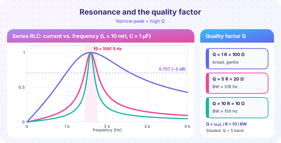
the impedance is the minimum possible, Z = R, the current is the maximum possible, I = V/R, and it is in phase with the source. Take L = 10 mH and C = 1 µF: ω₀ = 10 000 rad/s and f₀ = 1591.5 Hz.
Inside the circuit the energy sloshes between the inductor's magnetic field and the capacitor's electric field. The source only has to replace what the resistor dissipates.
Quality factor and bandwidth
The quality factor is
Q = ω₀ L / R = 1/(ω₀ R C) = (1/R) √(L/C)
With R = 20 Ω: Q = 10⁴ × 0.01 / 20 = 5. Larger Q (smaller R) means a sharper peak.
The half-power bandwidth is the width of the band between the two frequencies where the current falls to 1/√2 of its peak:
B = ω₂ − ω₁ = R/L rad/s, or B = f₀/Q in hertz.
For our example B = 20/0.01 = 2000 rad/s = 318 Hz. The exact half-power frequencies are ω = ∓α + √(α² + ω₀²) with α = R/2L = 1000 s⁻¹: ω₁ = 9050 rad/s (1440 Hz) and ω₂ = 11 050 rad/s (1759 Hz). Their difference is exactly 2000 rad/s, and f₀ is their geometric mean: √(ω₁ω₂) = 10 000.
Voltage magnification
At resonance the current is I = V/R. The voltage across the inductor is |V_L| = I ω₀ L = Q V and across the capacitor |V_C| = I/(ω₀ C) = Q V. With a 10 V RMS source and Q = 5: I = 0.5 A, and each of V_L and V_C is 50 V, five times the source. They are 180° apart, so they cancel and the loop equation is satisfied: V_R = 10 V. High-Q circuits can therefore produce dangerous voltages inside a "low voltage" circuit, and components must be rated accordingly.
Parallel resonance
Place L and C in parallel (an ideal "tank" circuit). At ω₀ = 1/√(LC) the inductor and capacitor currents cancel, so the combination draws no current from the source: its impedance is a maximum (infinite for ideal parts). Real inductors have resistance, so the peak is finite, but it can be hundreds of kilohms. Tank circuits set the frequency of oscillators and form the selective element in radio receivers. The quality factor of a parallel RLC with resistance R across it is Q = R/(ω₀ L). Notice that it is the opposite of the series case: a larger R gives a higher Q.
Tuning a radio
An AM broadcast at 1000 kHz must be picked out among stations spaced 10 kHz apart. Take an inductor L = 240 µH and adjust C until resonance matches the station: C = 1/(ω₀² L) = 1/((2π × 10⁶)² × 240×10⁻⁶) = 105.5 pF. Turning the tuning knob changes C and moves f₀. The needed Q is about f₀ / B = 1000 kHz / 10 kHz = 100: high enough to reject neighboring stations, yet wide enough to pass the speech and music sidebands. A very high Q would cut off the audio detail, which is the engineering trade-off.
Common misconceptions
"At resonance the impedance is zero." It is the minimum, equal to R; it is zero only if R = 0.
"A bigger resistor makes a better resonator." In a series circuit a bigger R gives lower Q and a broader, weaker peak.
"The source voltage is the largest voltage in the circuit." At resonance V_L and V_C are Q times larger.
Try it
The first program computes all the resonance numbers for the example, including the exact half-power frequencies, and the radio-tuning capacitance.
Press Run (or Ctrl + Enter) to see the result here.
Program input · what you'd type while the program runs
Type the answers before you press Run, one per line. Each time the program reads a line (with input()), it gets the next line from this box.
The second demo draws the resonance curve while you change R. The pink band shows the half-power bandwidth and the readouts show Q and B.
Check your understanding
Quick check · 6 questions
of 6 answered You scored / 6 · perfect!
-
1. The resonant frequency of a series RLC circuit is
Reactances cancel when ω L = 1/(ω C), giving ω₀ = 1/√(LC). -
2. At resonance the impedance of a series RLC circuit is
The reactances cancel, leaving only the resistance, which is the minimum impedance. -
3. L = 10 mH, R = 20 Ω, ω₀ = 10 000 rad/s. The quality factor is
Q = ω₀ L / R = 10⁴ × 0.01 / 20 = 5. -
4. A circuit has f₀ = 1 MHz and Q = 100. Its bandwidth is
B = f₀ / Q = 10⁶ / 100 = 10 kHz. -
5. A series RLC circuit with Q = 8 is driven by 5 V RMS at resonance. The voltage across the capacitor is
V_C = Q × Vs = 8 × 5 = 40 V. -
6. If you increase R in a series RLC circuit, the resonance curve becomes
Q = ω₀L/R falls as R rises, so the peak broadens.
Summary
- Series resonance at
ω₀ = 1/√(LC):Z = R, current maximum and in phase with the source. Q = ω₀ L / R = f₀ / B, with half-power bandwidthB = R/(2πL)hertz.V_LandV_CreachQtimes the source voltage at resonance.- Parallel resonance gives a maximum impedance; tuning a radio means adjusting
C(orL) to movef₀.
Next: Chapter 8 review
Track your progress
Create a free account to tick off lessons and pick up where you left off on any device.
of Circuit Analysis lessons completed