


















Lesson 36 of 48 · AC Circuits and Phasors
Impedance and AC Circuit Analysis
Extend Ohm's law to capacitors and inductors with complex impedance. Combine series and parallel elements and solve AC circuits with worked examples.
In a DC circuit a resistor relates voltage and current by one real number. In an AC circuit, capacitors and inductors also relate them, but with a phase shift and a dependence on frequency. Complex impedance packs all of this into one number, so the familiar rule V = I Z keeps working. Everything you learned in earlier chapters (voltage dividers, series and parallel rules, Kirchhoff's laws, nodal analysis and the theorems) carries over unchanged. Only the arithmetic uses complex numbers.
What you will learn
- The impedance of R, L and C and where each comes from.
- Resistance, reactance, impedance and admittance.
- Series and parallel combinations with complex numbers.
- A complete worked analysis with a phasor check using KVL.
Key terms
Impedance Z = V / I: complex, measured in ohms; Z = R + jX.
Reactance X: the imaginary part of impedance; positive for inductors, negative for capacitors.
Admittance Y = 1/Z: measured in siemens; Y = G + jB with conductance G and susceptance B.
Capacitive / inductive circuit: one whose net reactance is negative / positive.
Impedance of the three elements
Apply phasors to the element laws.
- Resistor.
v = R igivesV = R I, soZ_R = R. No phase shift. - Inductor.
v = L di/dtandd/dt → jωgiveV = jωL I, soZ_L = jωL = ωL ∠ 90°. The voltage leads the current by 90° and the magnitude grows with frequency: inductors pass low frequencies easily and resist high ones. - Capacitor.
i = C dv/dtgivesI = jωC V, soZ_C = 1/(jωC) = −j/(ωC) = (1/ωC) ∠ −90°. The current leads the voltage by 90°. The magnitude falls with frequency: capacitors pass high frequencies and block DC (ω = 0 makes the impedance infinite).
| Element | Impedance | Reactance X | Phase of Z |
|---|---|---|---|
| R | R |
0 | 0° |
| L | jωL |
+ωL |
+90° |
| C | 1/(jωC) |
−1/(ωC) |
−90° |
Series and parallel
Impedances combine like resistances:
- Series:
Z = Z₁ + Z₂ + … - Parallel:
1/Z = 1/Z₁ + 1/Z₂ + …, or add admittances:Y = Y₁ + Y₂ + … - Voltage divider:
V₁ = V Z₁ / (Z₁ + Z₂).
For a series R-L-C: Z = R + j(ωL − 1/(ωC)). The reactance can cancel when ωL = 1/(ωC): that is resonance, the subject of chapter 8.
Worked example: series RL
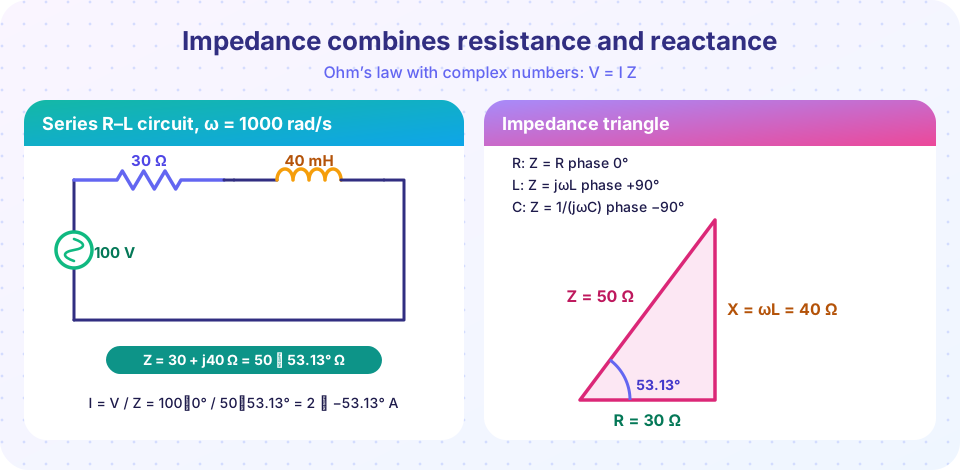
A source V = 100 ∠ 0° V (RMS) at ω = 1000 rad/s feeds a 30 Ω resistor in series with a 40 mH inductor.
- Reactance:
X_L = ωL = 1000 × 0.04 = 40 Ω. - Impedance:
Z = 30 + j40 = 50 ∠ 53.13° Ω. - Current:
I = V / Z = 100 ∠ 0° / 50 ∠ 53.13° = 2 ∠ −53.13° A. The current lags by 53.13°, as expected for an inductive circuit. - Element voltages:
V_R = R I = 60 ∠ −53.13° VandV_L = jX_L I = 40 ∠ 90° × 2 ∠ −53.13° = 80 ∠ 36.87° V. - Check with KVL:
V_R = 36 − j48,V_L = 64 + j48, sum= 100 + j0. ✓
Notice that |V_R| + |V_L| = 140 V is larger than the source. That is not an error: the voltages are 90° apart, so they add as the legs of a right triangle: √(60² + 80²) = 100. This surprises many learners the first time.
Adding a capacitor
Add a 25 µF capacitor in series. At 1000 rad/s, X_C = −1/(1000 × 25×10⁻⁶) = −40 Ω. Now Z = 30 + j40 − j40 = 30 Ω, purely resistive, and I = 100/30 = 3.33 A in phase with the source. The circuit is at resonance. The inductor voltage |V_L| = 40 × 3.33 = 133 V and the capacitor voltage 133 V are both larger than the source, but they are opposite in phase and cancel.
Parallel example
A 100 Ω resistor in parallel with a 10 µF capacitor at ω = 1000 rad/s. Admittances: Y_R = 0.01 S and Y_C = jωC = j0.01 S. Then Y = 0.01 + j0.01, so Z = 1/Y = 50 − j50 Ω = 70.7 ∠ −45° Ω. A 10 V source drives I = 10/70.7 = 0.141 A, leading the voltage by 45°.
AC analysis with all the tools
- Voltage divider and current divider formulas hold with complex impedances.
- Nodal analysis: write KCL with admittances. The matrix is complex; Python or any CAS solves it as easily as a real one.
- Mesh analysis: KVL with impedances.
- Thévenin and Norton:
Z_threplacesR_th. Maximum power transfer now needsZ_L = Z_th*(the complex conjugate), so a source with an inductive impedance wants a capacitive load component to cancel it. - Superposition: needed when sources have different frequencies. Solve each frequency separately and add the time-domain results, never the phasors.
Common misconceptions
"Impedance is just resistance with a fancy name." It is a complex number whose angle tells you the phase shift, and its magnitude depends on frequency (except for resistors).
"Voltages around a loop must add up in magnitude." KVL holds for phasors, not for magnitudes.
"A capacitor's impedance is positive imaginary." It is negative imaginary: −j/(ωC).
Try it
The first program is a complete AC solver for the series RL example, then the RLC and parallel cases. Change w, L or C and watch the phase and the resonance.
Press Run (or Ctrl + Enter) to see the result here.
Program input · what you'd type while the program runs
Type the answers before you press Run, one per line. Each time the program reads a line (with input()), it gets the next line from this box.
The second program draws the phasor diagram: the current as the reference direction, with the resistor and inductor voltages adding head-to-tail to the source voltage.
Press Run (or Ctrl + Enter) to see the result here.
Program input · what you'd type while the program runs
Type the answers before you press Run, one per line. Each time the program reads a line (with input()), it gets the next line from this box.
Check your understanding
Quick check · 6 questions
of 6 answered You scored / 6 · perfect!
-
1. The impedance of a 0.1 H inductor at ω = 500 rad/s is
Z_L = jωL = j × 500 × 0.1 = j50 Ω. -
2. The impedance of a 20 µF capacitor at ω = 1000 rad/s is
Z_C = 1/(jωC) = −j/(1000 × 20×10⁻⁶) = −j50 Ω. -
3. A series circuit has Z = 3 + j4 Ω and a 10 V RMS source. The current magnitude is
|Z| = 5 Ω, so I = 10 / 5 = 2 A. -
4. For a series RL circuit the current
Inductive reactance is positive, so Z has a positive angle and the current lags (ELI). -
5. In the parallel R–C example, why do we add admittances?
1/Z = Y, and parallel branches add admittances. It is the complex version of adding conductances. -
6. At resonance in the series RLC example the total impedance is
The inductive and capacitive reactances (±40 Ω) cancel, leaving only R = 30 Ω.
Summary
Z_R = R,Z_L = jωL,Z_C = 1/(jωC);V = I Zholds for phasors.- Series: add impedances; parallel: add admittances.
- Voltages add as phasors, not as magnitudes, so a part of the circuit can have more voltage than the source.
- All DC methods work in AC with complex numbers; different frequencies must be solved separately.
Next: AC power
Track your progress
Create a free account to tick off lessons and pick up where you left off on any device.
of Circuit Analysis lessons completed