


















Lesson 38 of 48 · AC Circuits and Phasors
Chapter 7 Review: AC Circuits and Phasors
Review sinusoids, phasors, impedance and AC power with a summary picture, a complete mixed example, a calculator widget and a ten-question quiz.
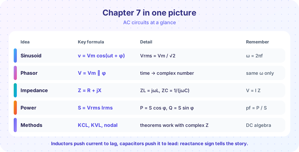
You started this chapter with waves that change every instant and ended with algebra on complex numbers. That is a big shift, and it is worth pausing to put the pieces together. This lesson recaps the key formulas, walks through one problem that uses all of them, and tests you with a mixed quiz.
What you will learn
- The full set of AC formulas on one page.
- A step-by-step routine for any single-frequency problem.
- How to catch typical mistakes (sign of reactance, RMS versus peak).
Key terms
Phasor: amplitude and phase as a complex number.
Reactance: imaginary part of impedance, +ωL or −1/(ωC).
Complex power: S = V I* = P + jQ.
Power-factor correction: adding reactance (usually a parallel capacitor) so the load looks more resistive to the line.
The routine
- Convert all sources to cosine form, choose RMS or peak, and write phasors.
- Compute
ω = 2πfand replace each element by its impedance. - Reduce or solve with series/parallel rules, dividers, nodal or mesh analysis, or Thévenin.
- Convert results back to the time domain if needed:
v(t) = √2 Vrms cos(ωt + φ). - Compute power:
S = V I*; checkP = I² RandQ = I² X.
Recap
| Idea | Formula |
|---|---|
| Sinusoid | v = Vm cos(ωt + φ), ω = 2πf, Vrms = Vm/√2 |
| Phasor | V = Vm ∠ φ; d/dt → jω, ∫ → 1/jω |
| Impedance | Z_R = R, Z_L = jωL, Z_C = 1/(jωC) = −j/(ωC) |
| Combination | series: ΣZ; parallel: ΣY, Y = 1/Z |
| Phase relations | ELI: V leads I in an inductor; ICE: I leads V in a capacitor |
| Power | P = V I cos φ, Q = V I sin φ, S = V I, pf = P/S |
| Correction | C = (Q − Q_target) / (ω V²) for a parallel capacitor |
A complete example
A 60 Hz, 120 V RMS source drives a load of 12 Ω in series with an inductor whose reactance is 16 Ω (L = 42.4 mH).
ω = 2π × 60 = 377 rad/s;Z = 12 + j16 = 20 ∠ 53.13° Ω.I = 120 ∠ 0° / 20 ∠ 53.13° = 6 ∠ −53.13° A.S = V I* = 120 × 6 ∠ 53.13° = 720 ∠ 53.13° VA = 432 + j576.- So
P = 432 W,Q = 576 var,pf = 0.6 lagging. Check:I² R = 36 × 12 = 432 W✓ andI² X = 36 × 16 = 576 var✓. - To reach unity pf add a parallel capacitor with
Q_C = 576 var:C = 576 / (377 × 120²) = 106 µF. The line current drops to432/120 = 3.6 A. - Time-domain current:
i(t) = 6√2 cos(377t − 53.13°) = 8.49 cos(377t − 53.13°) A.
Common misconceptions
"The sign of capacitive reactance is positive." It is negative: X_C = −1/(ωC).
"Mix peak and RMS freely." Every phasor in one problem must use the same convention; P = V I cos φ assumes RMS values.
"The power factor tells you whether the load is inductive or capacitive." The number alone does not; you must say lagging or leading.
Try it
This calculator handles any series R-L-C load at one frequency: impedance, current, power, power factor and the correction capacitor. Check it against the worked example.
Press Run (or Ctrl + Enter) to see the result here.
Program input · what you'd type while the program runs
Type the answers before you press Run, one per line. Each time the program reads a line (with input()), it gets the next line from this box.
The second demo lets you drag R and the reactance and see the impedance triangle, current angle and power factor change live.
Check your understanding
Quick check · 9 questions
of 9 answered You scored / 9 · perfect!
-
1. A circuit has Z = 4 − j3 Ω. It is
Negative reactance means the circuit is capacitive, so the current leads the voltage. -
2. The current in a 10 Ω resistor in series with a 10 Ω inductive reactance, from a 100 V RMS source, has magnitude
|Z| = √(10² + 10²) = 14.14 Ω, so I = 100 / 14.14 = 7.07 A. -
3. For that circuit the phase of the current relative to the voltage is
Z has angle +45°, so I = V/Z lags by 45°. -
4. The power factor of that circuit is
pf = R/|Z| = 10 / 14.14 = 0.707. -
5. The real power in that circuit is
P = I² R = 50 × 10 = 500 W. -
6. A 50 µF capacitor at 400 rad/s has impedance
X_C = −1/(ωC) = −1/(400 × 50×10⁻⁶) = −50 Ω. -
7. Which statement about RMS is true?
Peak = √2 × RMS = 14.14 V. -
8. Which pair describes a capacitor correctly?
ICE: in a capacitor the current leads the voltage by 90°. -
9. When adding sinusoids of the same frequency with phasors, you should
Phasors add as complex numbers; magnitudes and angles do not add separately.
Summary
- Phasors turn AC steady state into complex algebra; impedance extends Ohm's law.
Z_L = jωL,Z_C = −j/(ωC); series add impedances, parallel add admittances.- Power:
P = V I cos φ,Q = V I sin φ,S = V I*; correct the power factor with a parallel capacitor. - Next: how circuits respond across a whole range of frequencies.
Track your progress
Create a free account to tick off lessons and pick up where you left off on any device.
of Circuit Analysis lessons completed