


















Lesson 41 of 48 · Frequency Response and Resonance
Filters: Low-Pass, High-Pass, Band-Pass and Band-Stop
Design the four basic passive filters from resistors, capacitors and inductors, compute their cutoff and centre frequencies and check them with plots.
A filter is a circuit that passes some frequencies and blocks others. The first radio receivers were little more than an antenna and a tuned filter. Today filters clean the hum out of audio, separate bass from treble in speakers, stop aliasing in digital converters and keep noise out of sensors. With only resistors, capacitors and inductors you can build all four basic types, and the analysis is a voltage divider with impedances.
What you will learn
- Circuits and transfer functions for low-pass, high-pass, band-pass and band-stop filters.
- How to compute cutoff and centre frequencies and choose component values.
- What filter order means for steepness.
- Typical uses.
Key terms
Pass band / stop band: frequencies that get through / are blocked.
Cutoff frequency f_c: the −3 dB edge of the pass band.
Centre frequency f₀ and bandwidth: for band filters, the middle of the band and its −3 dB width.
Order: the number of poles; each adds −20 dB/decade of roll-off.
Low-pass filter
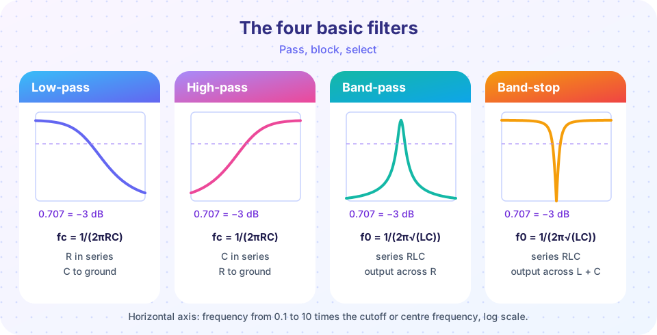
A resistor in series, then a capacitor to ground, with the output across the capacitor:
H(jω) = 1 / (1 + jωRC), f_c = 1 / (2πRC)
It passes low frequencies and rolls off at −20 dB/decade. Design example: to remove noise above about 3.4 kHz (the edge of the old telephone band) with C = 10 nF, pick R = 1/(2π × 3400 × 10⁻⁸) = 4.68 kΩ. The nearest standard value, 4.7 kΩ, gives f_c = 3.39 kHz.
Uses: anti-aliasing before an analog-to-digital converter, smoothing a PWM signal into a DC level, tone controls, removing high-frequency noise.
High-pass filter
Swap the two parts: capacitor in series, resistor to ground, output across the resistor:
H(jω) = jωRC / (1 + jωRC), f_c = 1 / (2πRC)
It blocks DC and slow drifts and passes high frequencies. A 1 µF capacitor with a 10 kΩ resistor has f_c = 15.9 Hz: a typical coupling capacitor that passes audio (20 Hz upward) between amplifier stages while blocking the DC bias of each stage.
Band-pass filter
Use a series RLC circuit and take the output across the resistor. At resonance the L and C cancel, so all of the input appears across R; far from resonance the reactances dominate and the current (and the voltage across R) falls.
H(jω) = R / [R + j(ωL − 1/(ωC))] = jωRC / (1 − ω²LC + jωRC)
f₀ = 1 / (2π√(LC)), Q = ω₀L/R, bandwidth B = f₀/Q = R/(2πL).
Example: L = 10 mH, C = 1 µF, R = 20 Ω: f₀ = 1591.5 Hz, Q = 10⁴ × 0.01/20 = 5, B = 318 Hz. The half-power edges are near 1440 Hz and 1759 Hz, almost centered on f₀. Radio tuners use the same principle: change C and the band moves to another station.
Band-stop (notch) filter
Take the output across the series L and C instead of across R. At resonance the series LC branch has zero impedance and the output is shorted: a deep notch.
H(jω) = (1 − ω²LC) / (1 − ω²LC + jωRC)
Uses: remove 50/60 Hz mains hum from a biological signal such as an ECG, or remove one interfering tone. The notch is narrow when Q is high.
Order and steepness
A single RC section is first order: the roll-off is gentle. Cascading sections makes the skirt steeper (second order −40 dB/decade, third order −60 dB/decade), but simple passive RC cascades also load each other and soften the corner. Better shapes come from carefully chosen Butterworth, Chebyshev and other designs, and from active filters (op-amps add gain and prevent loading), which you will meet in electronics courses. The principle remains the same: the output is a voltage divider of frequency-dependent impedances.
Comparing the four
| Filter | Pass | Block | Typical use |
|---|---|---|---|
| Low-pass | below f_c |
above | anti-aliasing, smoothing |
| High-pass | above f_c |
below | coupling, remove DC |
| Band-pass | around f₀ |
elsewhere | radio tuning, equalizers |
| Band-stop | elsewhere | around f₀ |
hum removal |
Common misconceptions
"A high-pass filter is the same circuit as a low-pass one." The two parts are swapped, which changes which impedance is across the output.
"A bigger capacitor gives a higher cutoff." The cutoff is 1/(2πRC), so a bigger C or R lowers it.
"A filter's load does not matter." A real load adds to the filter's output impedance and shifts the response; a good design takes it into account.
Try it
The first program computes the design values from this lesson and the gain of each filter at three frequencies.
Press Run (or Ctrl + Enter) to see the result here.
Program input · what you'd type while the program runs
Type the answers before you press Run, one per line. Each time the program reads a line (with input()), it gets the next line from this box.
The second program plots all four filters, each on a log frequency axis in decibels.
Press Run (or Ctrl + Enter) to see the result here.
Program input · what you'd type while the program runs
Type the answers before you press Run, one per line. Each time the program reads a line (with input()), it gets the next line from this box.
Check your understanding
Quick check · 5 questions
of 5 answered You scored / 5 · perfect!
-
1. In a first-order RC low-pass, where is the output taken?
The capacitor shorts high frequencies, so the voltage across it falls as the frequency rises. -
2. R = 8 kΩ, C = 2 nF. The cutoff frequency is about
fc = 1/(2π × 8000 × 2×10⁻⁹) = 9.95 kHz. -
3. Which filter blocks DC?
A high-pass filter has a series capacitor that passes no DC. -
4. A series RLC band-pass has L = 1 mH, C = 10 µF. Its centre frequency is
LC = 10⁻⁸, so √(LC) = 10⁻⁴ and f₀ = 1/(2π × 10⁻⁴) = 1592 Hz. -
5. A notch filter is used to
A band-stop (notch) filter attenuates a narrow band and passes everything else.
Summary
- Low-pass: R in series, output across C. High-pass: C in series, output across R. Both have
f_c = 1/(2πRC). - Series RLC: output across R gives band-pass, across L + C gives band-stop;
f₀ = 1/(2π√(LC)),B = R/(2πL). - Each pole adds −20 dB/decade of roll-off.
- Real designs consider the load and use better filter families or active circuits for sharp corners.
Track your progress
Create a free account to tick off lessons and pick up where you left off on any device.
of Circuit Analysis lessons completed