


















Lesson 22 of 49 · Wings and Finite Span Effects
Chapter 5 overview: from airfoils to wings
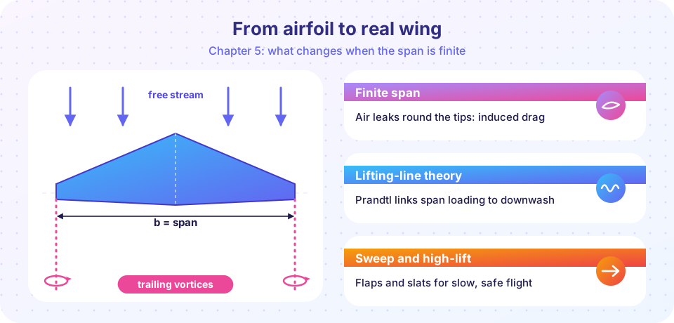
See the big picture of finite wings: tip vortices, induced drag, lifting-line theory, sweep and high-lift devices, with a visual map of the chapter.
So far you have treated lift as something an airfoil section does in a flow that is the same at every spanwise station. That is a two-dimensional idea: imagine a wing so long that it runs from wall to wall of a wind tunnel. Real wings end. The moment a wing has tips, air can leak from the high-pressure lower surface to the low-pressure upper surface, and the flow stops being two-dimensional. Everything in this chapter follows from that one fact.
What you will learn
- Why a finite wing sheds trailing vortices and how they produce downwash.
- How aspect ratio controls induced drag and lift slope.
- How Prandtl's lifting-line theory predicts the span loading of a straight wing.
- What wing sweep and taper do, and why high-lift devices exist.
The big picture in slides
Real wings have tips
Vortices change the flow
The price: induced drag
Predicting the loading
Shaping the wing
What each lesson covers
- The finite wing and induced drag: the physical picture. You meet tip vortices, downwash, the induced angle of attack and the formula for induced drag.
- Lifting-line theory: Prandtl's model of a wing as a bound vortex, the elliptical ideal, and a short program that solves the span loading of any straight wing.
- Sweep and high-lift devices: why most fast aircraft are swept, why that causes problems at low speed, and how flaps and slats fix them.
- Chapter 5 review: a one-page summary and a ten-question quiz.
Key terms
Span (b): the distance from one wing tip to the other.
Planform area (S): the wing area seen from above.
Aspect ratio (AR): span squared divided by area, AR = b² / S. For a rectangle it is span divided by chord.
Induced drag: the part of drag that comes with producing lift on a finite wing.
Try it
Aspect ratio is the single most useful number in this chapter. Compute it for three imaginary wings, then see what it implies for the ideal induced drag at the same lift coefficient.
Press Run (or Ctrl + Enter) to see the result here.
Program input · what you'd type while the program runs
Type the answers before you press Run, one per line. Each time the program reads a line (with input()), it gets the next line from this box.
Check your understanding
Quick check · 4 questions
of 4 answered You scored / 4 · perfect!
-
1. Why do real wings behave differently from a two-dimensional airfoil section?
The pressure difference between the lower and upper surfaces drives flow around the tips, which makes the flow three-dimensional. -
2. What is the aspect ratio of a wing with span 12 m and area 18 m²?
AR = b² / S = 144 / 18 = 8. -
3. Which wing has the lowest induced drag at a given lift coefficient, other things equal?
CDi = CL² / (π e AR), so it falls as aspect ratio rises. -
4. What is the main job of flaps and slats?
They raise the maximum lift coefficient so the aircraft can fly and land at lower speeds.
Summary
- A finite wing sheds tip vortices; they cause downwash and induced drag.
- Aspect ratio
AR = b² / Scontrols how large these effects are. - Lifting-line theory predicts span loading; sweep and flaps adapt the wing to real missions.
Track your progress
Create a free account to tick off lessons and pick up where you left off on any device.
of Aerodynamics lessons completed