


















Lesson 23 of 49 · Wings and Finite Span Effects
The finite wing and induced drag
Learn why a finite wing sheds tip vortices, how downwash tilts the lift vector, and how to compute induced drag from aspect ratio and lift coefficient.
An airfoil section produces lift because pressure is lower on top than underneath. On a wing that ends, that pressure difference has somewhere to go. Air from beneath curls around each tip toward the low-pressure upper side, forming a swirling vortex that trails behind the aircraft. This lesson explains how that vortex quietly changes the lift, adds a new kind of drag, and why long slender wings are so efficient.
What you will learn
- Why a finite wing sheds trailing vortices.
- How downwash creates an induced angle of attack and tilts the lift vector.
- How to compute induced drag from
CL,ARand the span efficiency factore. - Why aspect ratio also changes the lift slope of a wing.
Key terms
Trailing vortex: a rotating tube of air shed from the wing tip and carried downstream.
Downwash (w): the downward velocity the vortices induce at the wing.
Induced angle of attack (αᵢ): the small angle by which downwash tilts the local flow.
Span efficiency factor (e): a number up to 1 that measures how close the span loading is to the ideal elliptical shape.
Where the vortices come from
Underneath a lifting wing the pressure is slightly above ambient; above it the pressure is below ambient. Near the tip nothing separates those two regions, so air flows around the edge, outward under the wing and inward over it. The wing also carries circulation: a net rotation of the air around it that is the signature of lift. Helmholtz's vortex laws say a vortex line cannot simply end in the fluid, so wherever the circulation around the wing changes along the span, vortex filaments must stream off the trailing edge. Most of that vorticity rolls up into one strong vortex per side a short distance behind the wing.
You can see these vortices as condensation trails behind airliners, or as twisting wisps in humid air behind aircraft on approach. The pair is strongest when the aircraft is heavy, slow and clean, because that is when the lift coefficient is high. Air traffic control keeps spacing between aircraft partly because of their wakes.
Downwash and the tilted lift vector
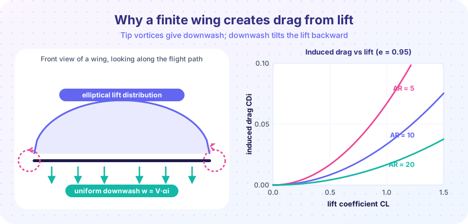
Two counter-rotating vortices, one from each tip, push the air between them downward, like two spinning rollers squeezing something between them. The air passing the wing therefore moves slightly downward as well as backward. Seen from the wing, the relative wind arrives from slightly below the free-stream direction.
The key consequence is a small angle, the induced angle of attack αᵢ, between the free-stream direction and the local flow direction. The wing section works in that local flow, so:
- Its effective angle of attack is
α_eff = α − αᵢ, smaller than the geometric angle. - The lift it produces is perpendicular to the local flow, not to the free stream. It is tilted backward by
αᵢ.
The backward tilt gives a component of the force along the free-stream direction: drag. This is induced drag, Dᵢ = L · tan αᵢ ≈ L · αᵢ. It is not caused by friction or separation. It is the cost of making lift with a wing of finite span, and it exists even in perfectly inviscid flow.
A formula you can use
For a wing with the ideal elliptical loading, Prandtl's theory (next lesson) gives:
αᵢ  = CL / (π · AR)
CDi = CL² / (π · AR)
Real wings are slightly worse. Introduce the span efficiency factor e:
CDi = CL² / (π · e · AR) with 0 < e ≤ 1
Read the formula in three ways. First, induced drag grows with the square of the lift coefficient: flying slowly (high CL) is expensive. Second, it falls in proportion to aspect ratio: doubling AR halves it. Third, because CL = W / (q S), induced drag in level flight is large at low speed and decreases as speed rises, while friction and pressure drag go the other way. That tension produces the best-glide and best-endurance speeds you will use in the projects.
A worked example. A glider has b = 15 m, S = 10 m², so AR = 225 / 10 = 22.5. At CL = 0.9 with e = 0.95:
CDi = 0.9² / (π · 0.95 · 22.5) = 0.81 / 67.2 ≈ 0.012
A short-span fighter-style wing with AR = 3.5 at the same lift coefficient and the same e would have CDi = 0.81 / (π · 0.95 · 3.5) ≈ 0.078, about six times larger.
Aspect ratio also changes the lift slope
The downwash lowers the effective angle of attack, so a finite wing makes less lift per degree than its airfoil section. With the section lift-curve slope a₀ (about 2π per radian for a thin airfoil) the finite-wing slope is:
a = a₀ / (1 + a₀ / (π · e · AR))
At AR = 6 and e = 1, a ≈ 2π / (1 + 2π/(6π)) = 6.28 / 1.333 = 4.71 per radian, about three quarters of the airfoil value. At AR = 20, a ≈ 6.28 / 1.1 = 5.71 per radian. At AR = 3, a ≈ 6.28 / 1.667 = 3.77 per radian. So long wings waste less lift to downwash and respond more strongly to a given change of angle.
Common misconceptions
"Induced drag is a kind of friction." It is not. It comes from the redirection of the lift vector and exists even without viscosity.
"Wing tip devices remove the vortices." Winglets and raked tips do not delete the tip vortex; they spread its strength and recover a little energy, effectively increasing the wing's effective span.
"The trailing vortices are an accident of wing design." They are a necessary consequence of lift: no spanwise change in circulation, no vortex sheet, no lift.
Try it
First, an interactive picture: change aspect ratio and lift coefficient and watch the induced angle and the tilted lift vector change. The widget demonstrates the formulas above with e = 0.95. The tilt angle is exaggerated eight times so you can see it.
Second, a drag-versus-speed chart: add induced drag to a constant parasite drag to see why flying slowly is costly. The numbers describe an illustrative light airplane.
Press Run (or Ctrl + Enter) to see the result here.
Program input · what you'd type while the program runs
Type the answers before you press Run, one per line. Each time the program reads a line (with input()), it gets the next line from this box.
Check your understanding
Quick check · 5 questions
of 5 answered You scored / 5 · perfect!
-
1. What causes the downwash at a finite wing?
The counter-rotating tip vortices induce a downward velocity at the wing. -
2. How does downwash change the lift vector?
Lift is perpendicular to the local flow, which is tilted by the induced angle, so the force has a component along the free stream. -
3. A wing has AR = 10, e = 0.9 and CL = 0.7. What is CDi?
CDi = 0.49 / (π · 0.9 · 10) = 0.49 / 28.27 ≈ 0.0173. -
4. If you double aspect ratio at the same CL and e, the induced drag coefficient
CDi is inversely proportional to AR. -
5. Why does induced drag decrease as an airplane speeds up in level flight?
Lift must equal weight, so CL = W / (q S) falls as speed grows, and CDi goes with CL².
Summary
- Pressure differences drive air around the tips; the wing sheds trailing vortices that induce downwash.
- Downwash reduces the effective angle of attack and tilts lift backward, creating induced drag.
CDi = CL² / (π e AR): grows withCL², falls with aspect ratio.- A finite wing has a smaller lift slope than its airfoil section:
a = a₀ / (1 + a₀/(π e AR)).
Next: Lifting-line theory
Track your progress
Create a free account to tick off lessons and pick up where you left off on any device.
of Aerodynamics lessons completed