


















Lesson 45 of 49 · Projects and Practice
Project 3: supersonic inlet and nozzle
Design the shock system of a supersonic inlet and size a converging-diverging nozzle: compute pressure recovery for ramp configurations, exit Mach, area ratio and thrust.
A jet engine cannot swallow supersonic air directly: its compressor needs subsonic flow at a Mach number of roughly 0.4 to 0.6. The inlet must slow the flow down, and every shock it uses along the way throws away some stagnation pressure, which becomes lost thrust. At the other end of the engine, a nozzle turns the hot, high-pressure gas back into a fast jet. This project uses the shock and isentropic relations of Chapter 6 to compare inlet designs and to size a nozzle, two classic problems of high-speed propulsion aerodynamics.
What you will learn
- How to chain oblique shocks and a final normal shock and compute total pressure recovery.
- Why multiple weak shocks outperform one strong one.
- How to design a converging-diverging nozzle: exit Mach, area ratio, mass flow and thrust.
- What the models leave out.
Key terms
Pressure recovery: the ratio of stagnation pressure after the inlet to the free-stream stagnation pressure, p₀,₂/p₀,∞.
Ramp: a wedge-shaped surface that turns the flow and creates an oblique shock.
Design point: the flight Mach number at which the shocks meet the cowl lip.
Ideal expansion: a nozzle whose exit pressure equals the ambient pressure.
Part 1: the inlet
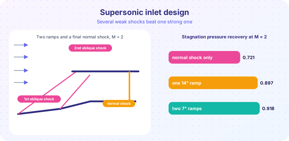
Consider free-stream Mach 2. A single normal shock in front of the engine leaves M = 0.577 and retains only 72.1% of the stagnation pressure (from Chapter 6). Alternatively let the flow first pass through a few oblique shocks created by ramps that turn the flow by a total angle θ:
- For each ramp compute the weak oblique shock from
Mandθ, using the θ-β-M relation. - The stagnation pressure ratio of the shock is the normal-shock ratio evaluated at the normal component
Mₙ = M sin β. - The Mach number after the ramp is
M₂ = Mₙ₂ / sin(β − θ). - After the last ramp, finish with a normal shock at the remaining Mach number, then diffuse subsonically to the engine face.
Multiplying the stagnation pressure ratios gives the total recovery. The key effect: the normal component Mₙ of each oblique shock is much smaller than M, and the loss in stagnation pressure grows very quickly with Mₙ (roughly like the cube of its excess over 1), so splitting the compression into several weak shocks saves much more than it costs. The theoretical optimum for a given number of ramps has the same normal Mach number across every shock. A modern inlet is more complicated, with variable ramps and bleed to manage the boundary layer, but the principle remains. As more ramps are added, the recovery approaches the isentropic limit of 1, but with growing weight and complexity.
Part 2: the nozzle
An ideally expanded nozzle accelerates gas isentropically from stagnation conditions (p₀, T₀) to ambient pressure p_a. Using the isentropic relations:
Mₑ = √( (2/(γ−1)) · [ (p₀/pₐ)^((γ−1)/γ) − 1 ] )
Aₑ / A* = (1/Mₑ) · [ (2/(γ+1)) (1 + (γ−1)/2 Mₑ²) ]^((γ+1)/(2(γ−1)))
Tₑ = T₀ / (1 + (γ−1)/2 · Mₑ²)           Vₑ = Mₑ · √(γ R Tₑ)
ṁ = 0.0404 · p₀ · A* / √T₀            (air, SI units, choked)      F = ṁ Vₑ
At a higher pressure ratio you get a higher exit Mach number and a bigger area ratio, which is why rocket nozzles at altitude are so large. If the nozzle is not ideally expanded (exit pressure differs from ambient) there is an extra pressure thrust term (pₑ − pₐ) Aₑ, and in the extreme, shocks form inside or outside the nozzle.
What the models leave out
Boundary layers on the ramps, shock/boundary-layer interaction (which can separate the flow), nozzle contour losses, real-gas effects and variable properties at high temperature. The nozzle assumes air with γ = 1.4; hot combustion gas has a lower effective γ and a different gas constant, which changes the numbers noticeably. Treat the results as the first step of a design process that continues with CFD (Chapter 8) and testing.
Common misconceptions
"A shock is inefficient, so inlets should avoid them." At supersonic speed some shock is unavoidable; the job is to spread compression across several weak shocks.
"More ramps are always better." Each ramp adds weight, drag and boundary-layer problems; real inlets use two to four.
"An oblique shock has no stagnation pressure loss." It always loses some, only a small amount for weak shocks.
Try it
First, the inlet calculator: total pressure recovery for different ramp arrangements at several Mach numbers, each with 15° of total turning.
Press Run (or Ctrl + Enter) to see the result here.
Program input · what you'd type while the program runs
Type the answers before you press Run, one per line. Each time the program reads a line (with input()), it gets the next line from this box.
Second, size a nozzle for given chamber conditions.
Press Run (or Ctrl + Enter) to see the result here.
Program input · what you'd type while the program runs
Type the answers before you press Run, one per line. Each time the program reads a line (with input()), it gets the next line from this box.
Check your understanding
Quick check · 4 questions
of 4 answered You scored / 4 · perfect!
-
1. Why does an inlet use several weak oblique shocks rather than one normal shock?
The normal component of each oblique shock is small, so the stagnation pressure loss is much lower. -
2. The Mach number needed at the compressor face is roughly
Compressors need subsonic flow at a moderate Mach number. -
3. For a normal shock at M = 2, the stagnation pressure ratio is about
p02/p01 = 0.7209 at M = 2. -
4. An ideally expanded nozzle has
Ideal expansion means pe = pa, so there is no pressure thrust term.
Summary
- Total pressure recovery is the product of the stagnation pressure ratios of each shock; splitting compression into several weak shocks preserves more.
- Exit Mach follows from the pressure ratio, area ratio from
Mₑ, and thrust fromṁ Vₑ. - Real inlets and nozzles add boundary-layer and gas-property effects that this model omits.
Next: Practice problems
Track your progress
Create a free account to tick off lessons and pick up where you left off on any device.
of Aerodynamics lessons completed