


















Lesson 10 of 49 · Overview and Materials
Tolerances, Fits and Surface Finish
Learn how dimensional tolerances, ISO IT grades, clearance and interference fits, thermal expansion and surface roughness Ra decide which process can make a part.
No process makes two parts exactly alike. A lathe leaves a shaft that differs from the next one by a few micrometers; a casting varies by a millimeter or more. A drawing therefore cannot say "25 mm", it must say "25 mm, give or take how much?". That "how much" is the tolerance, and it is one of the strongest drivers of manufacturing cost. This lesson shows how tolerances are written, how mating parts are given a controlled fit, how surface roughness is measured, and how to choose a process whose natural accuracy is good enough without paying for more.
What you will learn
- Write and read bilateral, unilateral and limit tolerances.
- Explain ISO IT grades and calculate clearance and interference for standard fits.
- Estimate the effect of temperature on dimensions with
ΔL = α L ΔT. - Read a surface roughness value Ra and match it to processes.
- Combine tolerances in an assembly using worst-case and statistical stack-up.
Key terms
Tolerance: the total permitted variation of a dimension, equal to the upper limit minus the lower limit.
Fit: the relationship between a hole and a shaft that mate, from loose clearance to tight interference.
IT grade: an ISO 286 international tolerance grade; a smaller number is a tighter tolerance.
Ra: the arithmetic average roughness, the mean absolute height of surface peaks and valleys, in micrometers.
Stack-up: the combined variation of several dimensions in an assembly.
Writing a tolerance
There are three common ways to write the same idea:
- Bilateral:
25.00 ± 0.05 mm. The part is good between 24.95 and 25.05 mm; tolerance is 0.10 mm. - Unilateral:
25.00 +0.10 / -0.00 mm. Used when one direction matters, such as a hole that must not be smaller than nominal. - Limit:
25.10 / 25.00 mm. The upper and lower limits are written directly.
Tolerance is the total band, 0.10 mm in each example above, not the plus-or-minus amount. A tighter tolerance costs more because the process must be slower, the machine more rigid, the tools replaced sooner, and the inspection more frequent. Cost typically rises steeply as tolerance shrinks, which is why designers specify only the tolerance they need.
ISO grades and fits
The ISO 286 system gives each nominal size range a series of standard tolerance widths named IT01 to IT18. For a nominal size between 18 and 30 mm the common ones are:
| Grade | IT5 | IT6 | IT7 | IT8 | IT9 | IT10 | IT11 |
|---|---|---|---|---|---|---|---|
| Width (µm) | 9 | 13 | 21 | 33 | 52 | 84 | 130 |
(The width grows with nominal size, because larger parts are harder to make precisely.) As a rough guide, IT5 to IT7 are precision work such as ground and honed parts, IT8 to IT11 are ordinary machined parts, and IT12 and larger suit rough work such as sand castings.
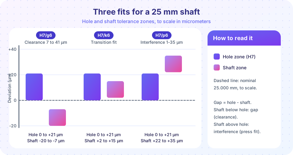
A fit is written as a hole symbol and a shaft symbol, such as H7/g6. The capital letter and number describe the hole; the lowercase letter and number describe the shaft. In the standard hole-basis system, the hole is H (its lower limit is the nominal size) and the shaft's position changes to make different fits. Hole-basis is popular because holes are made by drills and reamers of fixed size, while shafts are easy to turn to any size.
Worked example for a 25 mm nominal size
| Fit | Hole limits (mm) | Shaft limits (mm) | Result |
|---|---|---|---|
| H7/g6 | 25.000 to 25.021 | 24.980 to 24.993 | Clearance 7 to 41 µm: sliding fit |
| H7/k6 | 25.000 to 25.021 | 25.002 to 25.015 | From 19 µm clearance to 15 µm interference: transition fit |
| H7/p6 | 25.000 to 25.021 | 25.022 to 25.035 | Interference 1 to 35 µm: press fit |
Compute the clearance of H7/g6: smallest clearance = smallest hole minus largest shaft = 25.000 - 24.993 = 0.007 mm = 7 µm. Largest clearance = largest hole minus smallest shaft = 25.021 - 24.980 = 0.041 mm = 41 µm. Typical uses: H7/g6 for sliding guides, H7/k6 for gears and pulleys located accurately but still removable, H7/p6 for bushings pressed into housings.
Temperature changes size
Metals expand when warm. The change in length is ΔL = α L ΔT, where α is the coefficient of thermal expansion: about 11.7 × 10⁻⁶ /K for carbon steel and 23 × 10⁻⁶ /K for aluminum. A 100 mm aluminum bar that is 10 K above the 20 °C reference temperature is longer by 23 × 10⁻⁶ × 100 × 10 = 0.023 mm, or 23 µm. That is as large as the whole IT7 band. Precision measurement therefore uses a standard reference temperature of 20 °C, and inspection rooms are temperature controlled. A part machined warm and measured cold will be undersized.
Surface roughness
Every machined or cast surface is covered with tiny peaks and valleys. The most common single-number measure is Ra, the average height deviation from the mean line, in micrometers. The table gives typical ranges; actual values depend on the setup.
| Process | Typical Ra (µm) |
|---|---|
| Sand casting | 12 to 25 |
| Die casting | 0.8 to 3.2 |
| Milling | 0.8 to 6.3 |
| Turning | 0.4 to 3.2 |
| Grinding | 0.1 to 1.6 |
| Lapping or polishing | 0.025 to 0.2 |
A smoother surface improves fatigue life, sealing and wear but costs more. Roughness is also tied to tolerance: you cannot hold a 5 µm tolerance on a surface with 12 µm roughness.
Tolerance stack-up
Parts in an assembly add their variations. Suppose a stack of four parts each has a length tolerance of ±0.05 mm. The worst case assumes all errors line up: ±(4 × 0.05) = ±0.20 mm. A statistical (root-sum-square) estimate treats them as independent: ±√(4 × 0.05²) = ±0.10 mm. The statistical result is half the worst case and is valid when processes are stable and centered. Worst case is for safety-critical or low-volume assemblies; statistical stack-up allows looser, cheaper individual tolerances at high volume.
Choosing a tolerance in practice
A useful habit is to work backwards from function. Ask what the feature has to do: locate a part, seal a fluid, slide, or just clear another part. A hole that only has to let a bolt pass can be loose, since the bolt has clearance anyway. A bearing seat must hold its bearing without spinning, so it needs a transition or light interference fit. A sliding guide needs a clearance small enough to avoid rattle but large enough for a lubricant film.
Then ask which process can deliver that tolerance without extra steps. If a turned shaft can reliably hold IT8 and the design needs IT6, you must add grinding, and the price of the part rises. If instead the designer relaxes the fit to something a lathe can hold, the part costs less and the machine still works. The cheapest tolerance is the loosest one that still lets the product function, and it is the designer's responsibility to find it.
Common misconceptions
"Tighter is always better." Tolerance costs rise steeply; a tolerance tighter than the function needs is waste.
"A tolerance of ±0.05 mm means a 0.05 mm tolerance." The band is 0.10 mm wide.
"Roughness and tolerance are unrelated." A very tight dimension needs a surface smooth enough that the peaks do not eat the tolerance band.
Try it
The interactive tolerance zone viewer compares the three fits above, drawn to scale. Click a fit to see its numbers.
The second example compares worst-case and statistical stack-up with a quick Monte Carlo test.
Press Run (or Ctrl + Enter) to see the result here.
Program input · what you'd type while the program runs
Type the answers before you press Run, one per line. Each time the program reads a line (with input()), it gets the next line from this box.
Check your understanding
Quick check · 5 questions
of 5 answered You scored / 5 · perfect!
-
1. What is the tolerance (total band) of 40.00 ± 0.02 mm?
Upper limit 40.02 minus lower limit 39.98 gives 0.04 mm. -
2. In the hole-basis system, which hole symbol is used?
The hole-basis system uses H holes whose lower limit equals the nominal size. -
3. A 200 mm steel part (α = 11.7e-6 per K) warms by 15 K. By how much does it grow?
ΔL = 11.7e-6 × 200 × 15 = 0.0351 mm. -
4. Which process is best for Ra of about 0.2 µm?
Grinding and lapping reach sub-micrometer roughness, unlike casting and rough milling. -
5. Five parts each ±0.1 mm. What is the RSS stack-up estimate?
0.1 × √5 = 0.224 mm, compared with the worst case of 0.5 mm.
Summary
- A tolerance is the total permitted variation; cost climbs steeply as it shrinks.
- ISO IT grades and H/g, H/k, H/p style fits set clearance, transition or interference between mating parts.
- Temperature changes size by
α L ΔT; measure at the 20 °C reference. - Roughness Ra depends on the process, and tight tolerances need smooth surfaces.
- Worst-case stack-up is safe; RSS stack-up is realistic for stable processes.
Next: Chapter 2 Review
Track your progress
Create a free account to tick off lessons and pick up where you left off on any device.
of Manufacturing Processes lessons completed