


















Lesson 24 of 49 · Machining
The mechanics of cutting
How a chip forms: shear plane, rake angle, chip thickness ratio, Merchant's circle of forces, cutting power and specific cutting energy, with worked numbers.
Why does a lathe tool need so much power to peel off a thin curl of steel? Why do some cuts give long ribbons, others short broken chips, and others a rough, torn surface? The answers come from a surprisingly simple model of one cut, first worked out in the 1940s by Eugene Merchant and others. In this lesson you will use that model to compute the angle at which metal shears, the strain it suffers, the forces on the tool and the power the spindle must supply.
What you will learn
- How to describe one cut with five quantities: depth t0, chip thickness tc, rake angle α, shear angle φ and cutting speed V.
- How to compute the shear angle and shear strain from the chip thickness ratio.
- What the cutting force and thrust force are, and how Merchant's circle relates them to friction.
- How to find cutting power from force and speed, and from specific cutting energy.
- Why three different chip types appear and what each tells you.
Key terms
Orthogonal cutting: a simplified cut where the cutting edge is perpendicular to the cutting speed, so the process can be drawn in two dimensions.
Rake angle (α): the angle of the tool face measured from the line perpendicular to the cut surface. Positive rake leans the face away from the work and cuts more easily.
Shear angle (φ): the angle of the shear plane with the cut surface.
Chip thickness ratio (r): uncut thickness divided by chip thickness, r = t0 / tc. It is always below 1 for ordinary metal cutting, because the chip is thicker than the layer it came from.
Specific cutting energy (u): energy needed to remove a unit volume of material, in J/mm³ (the same as N/mm²).
One cut, five quantities
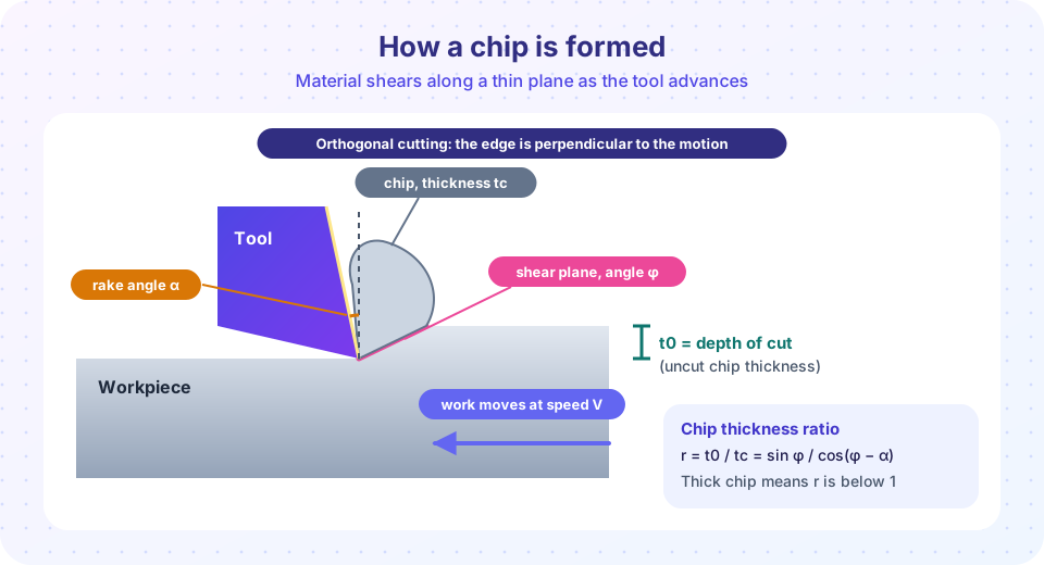
Imagine the tool is stationary and the workpiece slides toward it at cutting speed V. The tool removes a layer of uncut thickness t0 (this is the depth of cut in orthogonal cutting). Material ahead of the edge shears along the shear plane and leaves as a chip of thickness tc.
Because the metal volume is conserved and the chip is thicker than the layer it came from, the chip must be shorter than the length of the cut layer. It also flows more slowly than the workpiece moves. The chip thickness ratio captures this:
r = t0 / tc = sin φ / cos(φ − α)
You can measure tc with a micrometer on a chip, so r is the experimenter's way to find out how the cut went. Turn the formula around to get the shear angle:
tan φ = r cos α / (1 − r sin α)
Worked example 1: the shear angle
A cut has t0 = 0.25 mm, tc = 0.55 mm and rake angle α = 10°.
r = 0.25 / 0.55 = 0.4545.tan φ = 0.4545 × cos 10° / (1 − 0.4545 × sin 10°) = 0.4476 / 0.9211 = 0.486.φ ≈ 25.9°.
A small r (thick chip) means a small shear angle. That is bad news: a low shear angle gives a long shear plane, which needs more force and makes more heat.
Shear strain
Think of the metal on the shear plane as a deck of cards that slides. The strain is how far the top card moves relative to the thickness of the deck:
γ = cot φ + tan(φ − α)
With the numbers above, γ ≈ 2.06 + 0.28 = 2.34. That is huge. A tensile test specimen breaks at a strain well below 1, yet the chip survives a shear strain above 2 because the metal is under compression and heated, and because the shearing happens in a thin band at very high rate. This is why cutting energy is much higher than the energy needed to break the same piece in a tensile machine.
The forces on the tool
The tool feels two forces you can measure directly with a dynamometer:
- The cutting force
Fcacts along the cutting velocity. It does the work. - The thrust force
Ftacts perpendicular to the cut surface and pushes the tool away from the work. It does no work (nothing moves in that direction) but it bends the tool and the workpiece, so it affects accuracy.
Merchant drew the tool-chip interface as a circle of forces. The resultant R of all forces is the same on the tool face and on the shear plane (the chip is in equilibrium), so it can be resolved two ways:
Friction force on the tool face    F = Fc sin α + Ft cos α
Normal force on the tool face      N = Fc cos α − Ft sin α
Coefficient of friction            μ = F / N = tan β   (β = friction angle)
Shear force on the shear plane     Fs = Fc cos φ − Ft sin φ
Worked example 2: from force readings to friction
The dynamometer shows Fc = 1200 N and Ft = 500 N while cutting with α = 10°.
F = 1200 sin 10° + 500 cos 10° = 208 + 492 = 701 NN = 1200 cos 10° − 500 sin 10° = 1182 − 87 = 1095 Nμ = 701 / 1095 = 0.64, soβ = arctan 0.64 ≈ 32.6°
A friction coefficient of 0.64 is high, but it is typical for a chip sliding under enormous pressure on a hot tool face. Lubricating or coating the face lowers it and raises the shear angle, which is why cutting fluids and coatings improve cutting.
Merchant's rule of thumb
Merchant proposed that the metal chooses the shear angle that minimizes the cutting energy. That gives:
φ = 45° + α/2 − β/2
For α = 10° and β = 32.6° this predicts φ = 45 + 5 − 16.3 = 33.7°, which is higher than the 25.9° we measured. Real metals do not follow it exactly (it is a model), but it teaches the right lesson: more rake angle and less friction give a larger shear angle and an easier cut.
Power and specific cutting energy
Power is force times speed. Only the cutting force counts, because the thrust force has no motion along it:
P = Fc × V
With Fc = 1200 N and V = 120 m/min = 2 m/s, P = 2400 W = 2.4 kW. The spindle motor must supply this divided by the machine's efficiency, which is typically 70 to 90 percent.
A handier route is specific cutting energy, u = Fc / (w × t0), where w is the width of cut. For the example, with w = 3 mm, u = 1200 / (3 × 0.25) = 1600 N/mm² = 1.6 J/mm³. Handbooks tabulate u for each material: roughly a few tenths to about one J/mm³ for aluminum alloys, one to a few J/mm³ for steels, and more for hardened steels and titanium. Multiply by the material removal rate and you have power (check units: J/mm³ × mm³/s = W).
There is also a size effect: u rises when the chip gets very thin (below about 0.1 mm), because the edge is not perfectly sharp and ploughing consumes a larger fraction of the energy. This is one reason finishing cuts take more energy per unit volume than roughing cuts.
Where the energy goes
Nearly all the cutting energy becomes heat. Roughly: most (often 60 to 80 percent at ordinary speeds) is carried away in the chip, a smaller share goes into the tool, and the rest into the workpiece. That is a major reason high-speed machining can cut aluminum so well: the chip leaves so fast that most of the heat leaves with it.
Three chip types
- Continuous chips form with ductile metals at moderate to high speed and a positive rake. They give a good finish but long ribbons can tangle, so tool makers add chip breakers.
- Built-up edge (BUE) happens at low speeds, where bits of work material weld to the tool face and form a false cutting edge that grows and breaks off, leaving a rough surface. Raising the speed usually removes it.
- Segmented or discontinuous chips appear when cutting brittle materials (cast iron) or when cutting hard metals such as titanium at high speed. The cutting force fluctuates, which causes vibration.
Common misconceptions
"The chip is cut off like a wood shaving." The metal does not split along the edge. It deforms plastically on a shear plane, so the chip is thicker and shorter than the layer it came from.
"The thrust force is wasted power." It does no work in the direction of motion, so it does not enter the power equation, but it deflects the tool and ruins accuracy, so it matters for precision.
"A thicker chip means more efficient cutting." A thicker chip for a given layer means a lower chip ratio, a lower shear angle and more strain, so the cut is less efficient.
Try it
Enter your own readings and the calculator below returns the shear angle, strain and friction analysis from the equations of this lesson. It uses the same model as the worked examples, so it also shows you where Merchant's rule disagrees with measurements.
Press Run (or Ctrl + Enter) to see the result here.
Program input · what you'd type while the program runs
Type the answers before you press Run, one per line. Each time the program reads a line (with input()), it gets the next line from this box.
The second demo draws how the shear angle depends on the rake angle and the friction angle according to Merchant's rule.
Press Run (or Ctrl + Enter) to see the result here.
Program input · what you'd type while the program runs
Type the answers before you press Run, one per line. Each time the program reads a line (with input()), it gets the next line from this box.
Check your understanding
Quick check · 5 questions
of 5 answered You scored / 5 · perfect!
-
1. A cut has uncut thickness 0.20 mm and chip thickness 0.50 mm. What is the chip thickness ratio r?
r = t0 / tc = 0.20 / 0.50 = 0.4. It is below 1 because the chip is thicker than the layer it came from. -
2. Which force does NOT appear in the power equation P = Fc × V?
Power is force times velocity along the force. The cutting force acts along the velocity, so it counts. The thrust force is perpendicular to the motion and does no work, even though it deflects the tool. -
3. What happens to the shear angle when friction on the tool face is reduced and the rake angle is unchanged?
In Merchant's rule φ = 45° + α/2 − β/2, a smaller friction angle β raises φ. A larger shear angle means a shorter shear plane and a lower cutting force. -
4. At which condition is a built-up edge most likely?
At low speed the interface is cooler, bits of the ductile workpiece weld to the tool face and form a false edge. Raising the speed usually cures it. -
5. A cut removes material with specific cutting energy 2 J/mm³ at a removal rate of 5,000 mm³/s. What power is needed at the cutting edge?
Power equals energy per volume times volume per second: 2 J/mm³ × 5,000 mm³/s = 10,000 W = 10 kW.
Summary
- A chip forms by shear on a plane at angle φ; the chip thickness ratio
r = t0/tc = sin φ / cos(φ − α)gives φ from a simple measurement. - Shear strain
γ = cot φ + tan(φ − α)is large, which explains why cutting takes much more energy than a tensile test. - Forces resolve through Merchant's circle: friction
F = Fc sin α + Ft cos α, normalN = Fc cos α − Ft sin α,μ = F/N. - Power is
Fc × V, or specific cutting energy times removal rate. - Positive rake and low friction give a bigger shear angle and an easier cut; chip type tells you about speed and material.
Track your progress
Create a free account to tick off lessons and pick up where you left off on any device.
of Manufacturing Processes lessons completed