


















Lesson 33 of 49 · Additive Manufacturing
Additive manufacturing at a glance
What additive manufacturing is, the seven ISO/ASTM process categories, how a digital model becomes a printed part, and when 3D printing beats traditional manufacturing.
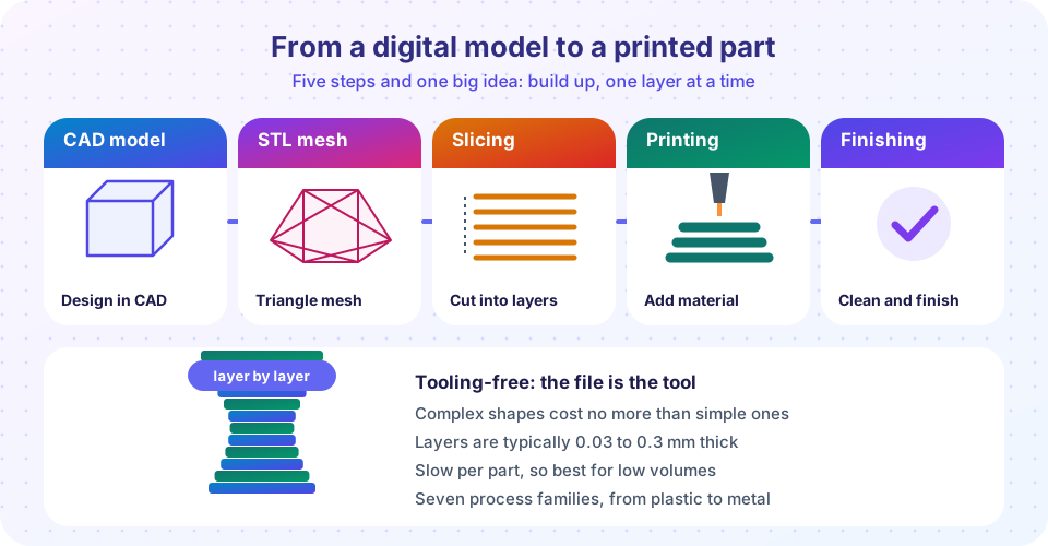
Every process in the earlier chapters of this course either starts with too much material and removes some (machining), or pours or presses material into a shape defined by a mold or die (casting, forging). Additive manufacturing (AM), popularly called 3D printing, does neither. It builds a part by adding material, layer by layer, directly from a digital model. No mold, no die, no fixture for the cutting tool to reach around: the file is the tool.
That one change affects what you can make (shapes that cannot be cast or cut), how fast you can iterate (a new design is a new file), and when it pays (low volumes win, high volumes lose). This chapter explains the main processes, the physics that limit them, and the economics that decide when to use them.
What you will learn
- What additive manufacturing is and how it differs from subtractive and formative processes.
- The seven process categories defined by ISO/ASTM 52900.
- The digital chain from CAD to a printed part, and what an STL file contains.
- The main strengths and limits of AM.
Key terms
Additive manufacturing: building parts by joining material layer upon layer from 3D model data.
STL file: a mesh of triangles describing the surface of a solid, the most common file for printing.
Slicing: software step that cuts the mesh into layers and generates the tool path for each.
Support structure: temporary material that holds overhangs in place during the build.
Post-processing: everything after the print: support removal, heat treatment, machining, surface finishing.
A short history
The first commercial process was stereolithography (SLA). Charles Hull patented it in 1984 and used it to build a part in 1986, founding the company 3D Systems. He also defined the STL file format, which is still in everyday use. In the late 1980s and 1990s powder bed fusion (SLS) and fused deposition modeling (FDM) followed. Expiring patents in the late 2000s let low-cost FDM printers reach homes and schools, and industrial metal printing grew quickly in aerospace, medicine and tooling.
The seven process categories
The international standard ISO/ASTM 52900 groups all AM processes into seven categories, named by how layers are formed:
| Category | How it works | Typical materials | Examples |
|---|---|---|---|
| Material extrusion | A heated nozzle pushes material out in lines | Thermoplastics | FDM, FFF |
| Vat photopolymerization | Light cures liquid resin | Photopolymers | SLA, DLP |
| Powder bed fusion | A laser or electron beam fuses powder | Nylon, metals | SLS, LPBF, EBM |
| Material jetting | Droplets are jetted and cured | Photopolymers, wax | PolyJet |
| Binder jetting | A binder glues powder together | Sand, metal, ceramic | Sand cores, metal parts after sintering |
| Directed energy deposition | A beam melts material as it is fed | Metal wire or powder | Large part repair, cladding |
| Sheet lamination | Sheets are bonded and cut | Paper, metal foil | Laminated object manufacturing |
The next two lessons explore them: polymer processes and metal processes with design for AM.
From CAD to part
- Design a solid in CAD software (or scan a real object).
- Export to STL (or 3MF, which also stores units, color and materials). The surface is approximated by triangles; finer triangles give smoother curves and larger files.
- Orient and support the part on the build platform. Orientation affects surface quality, strength, support volume and print time.
- Slice into layers of fixed thickness and compute the tool path for each, giving the machine instructions much like the G-code of a CNC machine.
- Build. The machine deposits, melts or cures one layer, the platform shifts by one layer thickness, and the process repeats.
- Post-process: remove from the platform, remove supports, clean, heat treat or machine critical surfaces and finish.
Strengths and limits
Strengths: no tooling cost; geometric freedom (internal channels, lattices, organic shapes); part consolidation (an assembly of many parts printed as one, as in some jet engine fuel nozzles); customization (dental aligners, hearing aids, patient-specific implants); fast design iteration; on-demand spare parts.
Limits: slow build rates; limited part size; stair-stepped surfaces and rough finishes; material properties that depend on direction (anisotropy) and on process parameters; the need for post-processing; and high cost per part at volume.
Three ways to make a shape
Why layers help
Why layers hurt
Common misconceptions
"3D printing replaces all other manufacturing." AM suits low volumes and complex shapes. For thousands of identical simple parts, molding and machining remain far cheaper.
"Printed parts are as strong as machined parts." Properties vary with process and direction, and many printed metals need heat treatment or hot isostatic pressing to match wrought material.
"The STL file defines the part completely." It describes only the surface. Material, orientation, layer height and process settings, all absent from an STL, change the result a lot.
Try it
Choose a layer height and see how the stack, the number of layers and the (very rough) print time change for a 50 mm tall part. The time model assumes a constant 40 seconds per layer, which is only an illustration.
Second, see what an STL file really is. A solid is just a list of triangles; this script computes the volume and surface area of a 10 mm cube from its 12 triangles.
Press Run (or Ctrl + Enter) to see the result here.
Program input · what you'd type while the program runs
Type the answers before you press Run, one per line. Each time the program reads a line (with input()), it gets the next line from this box.
Check your understanding
Quick check · 5 questions
of 5 answered You scored / 5 · perfect!
-
1. Which ISO/ASTM category does FDM belong to?
FDM pushes heated thermoplastic through a nozzle, which is material extrusion. -
2. What does an STL file store?
STL stores only the surface mesh. Layer height and tool paths are produced later by the slicing software. -
3. Which is a typical strength of additive manufacturing?
Parts come from a digital file with no mold or die, which suits low volumes and complex shapes. Cost per part at volume and finish are typical weaknesses. -
4. A 60 mm part is printed with 0.2 mm layers. How many layers are needed?
60 / 0.2 = 300 layers. -
5. Which step comes right after orienting the part on the build platform?
After orientation and supports, the slicer cuts the model into layers and computes the tool path for each.
Summary
- AM builds parts by adding material layer by layer from a digital model; it needs no tooling.
- ISO/ASTM 52900 defines seven categories: extrusion, vat photopolymerization, powder bed fusion, material jetting, binder jetting, directed energy deposition and sheet lamination.
- The chain is CAD, STL, orientation, slicing, build and post-processing.
- AM shines for complex, custom and low-volume parts, and loses on speed, surface finish and cost at volume.
Track your progress
Create a free account to tick off lessons and pick up where you left off on any device.
of Manufacturing Processes lessons completed