


















Lesson 16 of 49 · Casting and Molding
Plastic Injection Molding: Cycle, Cooling and Clamp Force
Understand the injection molding machine and cycle, estimate cooling time from wall thickness, size clamp force, and recognize common molding defects and design rules.
Look at a plastic bottle cap, a pen, a phone case, a toy brick. Almost certainly each of them was injection molded. The process is conceptually the die casting of plastics: melt pellets, inject the melt into a steel mold, wait for it to cool, open the mold and eject the part. Yet because plastic melt is thick like honey, thermally insulating and extremely sensitive to cooling, the engineering details differ from metal casting. This lesson follows one molding cycle from start to finish, derives the cooling-time estimate that drives cycle time, and shows how to size the clamping force of a press.
What you will learn
- Name the parts of an injection molding machine and the stages of the cycle.
- Estimate cooling time for a flat wall and see how thickness controls it.
- Calculate clamp force from cavity pressure and projected area.
- Link common molding defects to causes and apply basic design rules.
Key terms
Plasticizing: melting and mixing the polymer as a rotating screw moves it forward in a heated barrel.
Packing (holding): continuing to push melt in as the part cools so that shrinkage is compensated.
Gate: the small opening where melt enters the cavity.
Runner: the channel from the nozzle to the gate; in a cold-runner mold it is ejected with the part, in a hot-runner mold it stays molten.
Cavity pressure: the pressure inside the mold cavity during filling and packing.
The machine
An injection molding machine has two main units. The injection unit is a heated barrel containing a reciprocating screw. Plastic pellets fall from a hopper onto the screw; as it turns, friction and barrel heaters melt the polymer and push it to the front. The screw then acts like a plunger and drives the melt through the nozzle into the mold. The clamping unit holds the two mold halves shut and opens them to eject the part. The mold itself has a cavity, cooling channels carrying water, ejector pins, and venting for air.
Machines are classified by the tonnes of clamping force they provide, from a few tonnes for micro-parts to thousands of tonnes for car bumpers and crates.
The cycle
One molding cycle
- Close
- Inject
- Pack
Then finish
- Cool
- Open
- Eject
- Close and clamp the mold.
- Inject. The screw advances and the melt fills the cavity in a second or two, typically at speeds that avoid freezing in thin sections.
- Pack and hold. Pressure is maintained until the gate freezes, pushing in extra melt as the plastic shrinks.
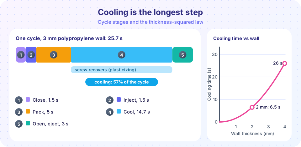
- Cool. The part cools until it is stiff enough to eject. While it cools, the screw rotates backward and prepares the next shot, so plasticizing overlaps cooling.
- Open the mold.
- Eject the part, close, repeat.
Typical total cycles are 10 to 60 seconds for small and medium parts; very thin-walled packaging can run in a few seconds. Cooling dominates the cycle, often more than half of it, so anything that cuts cooling time raises output.
Estimating cooling time
Heat flows from the hot melt into the cooled mold walls. For a flat wall of thickness h, with the melt injected at T_i, the mold wall held at T_w, and the part ejected when its centerline has cooled to T_x, a standard conduction result is:
t_c = (h² / (π² α)) × ln[ (4/π) × (T_i - T_w) / (T_x - T_w) ]
Here α is the thermal diffusivity of the polymer (about 0.08 to 0.10 mm²/s for polypropylene and similar plastics). The key feature is the factor h²: cooling time grows with the square of wall thickness.
Worked example
Polypropylene wall of thickness h = 2 mm, α = 0.09 mm²/s, T_i = 230 °C, T_w = 30 °C, T_x = 90 °C.
h² / (π² α) = 4 / (9.87 × 0.09) = 4.50 s.- The logarithm:
(4/π) × (200 / 60) = 1.273 × 3.333 = 4.244, andln 4.244 = 1.446. t_c = 4.50 × 1.446 = 6.5 s.
Halve the thickness to 1 mm and the cooling time falls to a quarter, about 1.6 s. This is why molders push designers toward thin, uniform walls.
Clamp force
The pressure of the melt inside the cavity pushes the mold halves apart over the part's projected area, so the clamp must exceed:
F = p_cavity × A_projected
Typical average cavity pressures range from about 20 to 80 MPa depending on the plastic, wall thickness and flow length. For a lid of 120 mm × 80 mm (projected area 9,600 mm²) in a two-cavity mold with a cavity pressure of 35 MPa: A = 2 × 9,600 = 19,200 mm², F = 35 × 19,200 = 672,000 N = 672 kN, about 69 tonnes-force. Add a margin of 10 to 20 percent and choose an 80 to 100 tonne press. Too little clamp force lets the mold flash open, leaving thin fins of plastic on the parting line.
Shrinkage and warpage
Plastics shrink as they cool: roughly 0.4 to 0.7 percent for amorphous ABS and 1 to 2 percent or more for semi-crystalline polypropylene. The mold cavity is made larger to compensate, so every plastic needs its own shrink factor. Uneven cooling or flow orientation causes different shrinkage in different places, which warps the part. Uniform wall thickness and balanced cooling are the best defenses.
Typical defects
| Defect | Appearance | Common causes | Fixes |
|---|---|---|---|
| Short shot | Cavity not filled | Low melt temperature, low pressure, tiny vents, thin walls | Raise temperature or pressure, widen gate, vent |
| Flash | Thin fin at parting line | Clamp force too low, worn mold, too much pressure | Increase clamp, repair mold |
| Sink mark | Dimple over a thick section | Thick area shrinks after the skin freezes | Thin the section, longer packing |
| Weld line | Visible line where flows meet | Cold melt fronts | Hotter melt, moved gate |
| Warpage | Part bends | Uneven cooling or wall thickness | Uniform walls, balanced cooling |
| Burn mark | Black streak | Trapped air compressed and ignited | Add vents, slow the injection |
| Jetting | Snake-like flow pattern | Melt shoots through a small gate | Slower fill, gate position |
Design for molding
A few rules produce better parts: keep wall thickness uniform (typically 1 to 4 mm for most parts), add ribs instead of thick sections for stiffness (ribs about half to two-thirds of the wall thickness to avoid sink), give draft of 1 to 2 degrees so the part ejects, round all inside corners, and avoid undercuts that need slides in the mold. Mold cost depends on complexity but is often in the tens to hundreds of thousands of currency units, so the process is economical for large volumes, in line with the break-even logic of Chapter 1.
Common misconceptions
"Thick walls make stronger parts." Thick walls cool slowly, sink and warp. Use ribs and gussets for stiffness.
"Plastic is injected cold and melts in the mold." The polymer is melted in the barrel; the mold is kept cold to freeze it.
"Faster injection is always better." Too fast causes jetting, burn marks and high stresses; too slow causes short shots.
Try it
Slide the wall thickness and see cooling time, an estimated cycle time and the hourly output of a four-cavity mold. The overhead times are assumed round values.
The second example plots cooling time against wall thickness for two plastics, using assumed diffusivities.
Press Run (or Ctrl + Enter) to see the result here.
Program input · what you'd type while the program runs
Type the answers before you press Run, one per line. Each time the program reads a line (with input()), it gets the next line from this box.
Check your understanding
Quick check · 5 questions
of 5 answered You scored / 5 · perfect!
-
1. Which stage normally takes the largest share of the molding cycle?
The plastic must cool until it is rigid enough to eject, which usually takes more than half the cycle. -
2. A wall is made twice as thick. Roughly how does the cooling time change?
Cooling time is proportional to h², so doubling thickness quadruples it. -
3. Cavity pressure 40 MPa on a projected area of 10,000 mm². The clamp force required is:
40 N/mm² × 10,000 mm² = 400,000 N = 400 kN. -
4. A thin fin of plastic on the parting line is called:
Flash forms when melt escapes through the parting line because the clamp force is too low or the mold is worn. -
5. What is the best way to stiffen a part without causing sink marks?
Ribs add stiffness without large thick sections, and being thinner than the wall they avoid sink marks.
Summary
- Injection molding melts pellets with a screw, injects the melt into a cooled steel mold, and ejects the frozen part.
- Cooling time
t_c ≈ h² / (π² α) · ln[...]scales with thickness squared and dominates the cycle. - Clamp force
F = p × A_projectedmust exceed the pressure that tries to open the mold. - Uniform walls, ribs, draft and venting prevent most defects.
- Mold cost is high, so molding suits large volumes.
Next: Chapter 3 Review
Track your progress
Create a free account to tick off lessons and pick up where you left off on any device.
of Manufacturing Processes lessons completed