


















Lesson 25 of 49 · Machining
Turning, milling and drilling: speeds, feeds and time
Calculate spindle speed, feed rate, material removal rate, machining time, power and surface roughness for turning, milling and drilling, with worked shop examples.
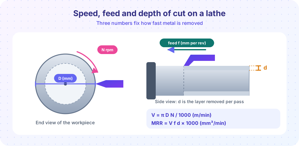
A machinist at a lathe does not guess at the settings. Three numbers (cutting speed, feed and depth of cut) decide how fast metal comes off, how much power the machine needs, how long the tool lasts and how smooth the surface looks. Once you know how those numbers connect, you can estimate the time and cost of a part before you ever touch a machine. This lesson turns the pictures of the previous lesson into working formulas for the three most common operations.
What you will learn
- How to convert between cutting speed (m/min) and spindle speed (rpm).
- How to compute feed rate, material removal rate and machining time for turning, milling and drilling.
- How to estimate spindle power from removal rate and specific cutting energy.
- How feed and nose radius set the theoretical surface roughness.
- How to choose sensible starting values for a new job.
Key terms
Spindle speed (N): revolutions per minute of the spindle (rpm).
Feed per revolution (f) and feed per tooth (fz): distance the tool advances per turn, or per cutting edge per turn.
Feed rate (vf): linear speed of the table or tool in mm/min.
Material removal rate (MRR): volume of metal removed per unit time, in mm³/min or cm³/min.
Nose radius (r): rounded corner of a turning insert; a bigger radius gives a smoother finish at the same feed.
Cutting speed and spindle speed
Cutting speed is the speed of the edge relative to the surface being cut. Because a point on a circle of diameter D travels π D each turn, and the spindle makes N turns per minute:
V = π D N / 1000      (V in m/min, D in mm, N in rpm)
N = 1000 V / (π D)
The 1000 converts millimeters to meters. Machinists think in V because the tool material and the workpiece material fix a sensible cutting speed, regardless of the diameter. A small drill and a large cutter need the same V but very different N.
Starting values for coated carbide inserts (these are rough starting ranges, not guarantees; always check the tool maker's catalog): aluminum alloys 250 to 600 m/min, low-carbon steel 150 to 250, stainless steel 80 to 180, titanium alloys 40 to 90. High-speed-steel (HSS) tools run much slower, on the order of 20 to 40 m/min for steel.
Worked example 1: spindle speed
You are turning a 40 mm steel bar with a carbide insert at V = 180 m/min.
N = 1000 × 180 / (π × 40) = 1,432 rpm.
When the diameter shrinks to 30 mm, the same V needs N = 1,910 rpm. CNC lathes do this automatically with constant surface speed mode (G96).
Turning: removal rate, power and time
Each revolution the tool removes a ring of cross-section f × d. The metal removed per minute is that cross-section times the cutting speed:
MRR = V × f × d × 1000 (mm³/min, with V in m/min, f and d in mm)
Worked example 2: a roughing cut
V = 180 m/min, f = 0.2 mm/rev, d = 2 mm:
MRR = 180 × 0.2 × 2 × 1000 = 72,000 mm³/min = 72 cm³/min = 1,200 mm³/s.- Take specific cutting energy
u = 2.5 J/mm³(a typical assumption for mild steel; real values vary with material, rake and chip thickness). - Cutting power
P = MRR × u = 1,200 × 2.5 = 3,000 W = 3 kW. - With a spindle drive efficiency of 80 percent, the motor must supply
3.0 / 0.8 = 3.75 kW.
Always check this against the machine's rated power. A small bench lathe with a 1.5 kW motor cannot run this cut, however sharp the tool. It can run it at half the depth.
Machining time
The tool travels the cut length L at feed rate f × N:
Tm = L / (f × N) (minutes)
For L = 150 mm, f = 0.2 mm/rev and N = 1,432 rpm, the feed rate is 286 mm/min, so Tm = 150 / 286 = 0.52 min, about 31 seconds. Real planning adds approach and over-travel distances to L (a few millimeters), the time for tool changes and the loading time.
Surface roughness from feed
Each revolution the tool leaves a tiny groove, like threads of a very fine screw. For a tool with nose radius r, the theoretical arithmetic-average roughness is approximately:
Ra ≈ f² / (32 r)
With f = 0.2 mm and r = 0.8 mm: Ra = 0.04 / 25.6 = 0.00156 mm = 1.6 µm. Halve the feed and the roughness drops to a quarter, 0.4 µm. That makes feed the main control for finish: roughing uses large f and d, finishing uses small f and a large nose radius. Real roughness is usually larger than this ideal value because of vibration, built-up edge and tool wear, so treat the formula as a lower limit.
Milling: feed per tooth
A milling cutter of diameter D with z teeth spins at N rpm. Each tooth takes a small bite fz (feed per tooth) as it passes the work. The table must therefore move at:
vf = fz × z × N (mm/min)
Milling has two widths. The axial depth ap is how deep the cutter goes along its axis; the radial width ae is how much of its diameter is engaged. The removal rate is:
MRR = ae × ap × vf
Worked example 3: a pocketing cut
A 20 mm, 4-tooth carbide end mill cuts aluminum at V = 120 m/min (a conservative value).
N = 1000 × 120 / (π × 20) = 1,910 rpm.- With
fz = 0.08 mm/tooth:vf = 0.08 × 4 × 1,910 = 611 mm/min. - With
ae = 10 mmandap = 5 mm:MRR = 10 × 5 × 611 = 30,550 mm³/min.
Up-milling and down-milling. In up (conventional) milling the tooth starts a cut with zero thickness and finishes at maximum, so it rubs before it cuts. In down (climb) milling the tooth enters at maximum thickness and leaves at zero, which gives a better finish and longer tool life, but it needs a machine with very little backlash because the cutter tends to pull the table forward. Modern CNC machines with ball screws normally use climb milling.
Drilling
A twist drill has two edges and removes material at the tip. The speed formula is the same, with D the drill diameter. The feed per revolution f is typically 0.01 to 0.05 times the diameter for HSS drills in steel.
Worked example 4: a through hole
A 10 mm HSS drill in steel at V = 30 m/min and f = 0.15 mm/rev:
N = 1000 × 30 / (π × 10) = 955 rpm.vf = f × N = 0.15 × 955 = 143 mm/min.- The drill tip (a 118° point) is about
0.3 D = 3 mmlong, so a 20 mm thick plate needsL = 20 + 3 = 23 mmof travel:Tm = 23 / 143 = 0.16 min, about 10 seconds.
For deep holes (depth greater than about three times the diameter) the drill must withdraw periodically, a peck cycle, so chips can leave the flutes. Without it, chips jam, the temperature spikes and the drill breaks.
How to choose settings
- Pick the cutting speed V from the tool material and workpiece material.
- Pick the feed from the finish you need (roughing: large; finishing: small) and from the tool's recommended range.
- Pick the depth of cut from how much stock is left and what the machine can support.
- Check power against the machine and rigidity against the setup (a long thin part bends away from the tool).
- Estimate tool life (next lesson) and adjust V.
Common misconceptions
"Spindle speed should be the same for all diameters." The cutting speed at the edge is what matters, so a small drill needs a much higher rpm than a large one.
"Doubling the depth of cut doubles tool wear." Depth of cut affects the heat much less than cutting speed does. Removal rate rises with depth almost for free; it mainly raises the force and power.
"Feed only affects time." Feed is also the dominant factor in surface roughness.
Try it
First, an interactive calculator. Move the sliders to see how settings change the spindle speed, removal rate, time, power and surface roughness. It uses the formulas from this lesson, with fixed assumptions for the specific energy and efficiency.
Next, compare the three operations from the worked examples in one script, and plot how roughness falls with feed for three nose radii.
Press Run (or Ctrl + Enter) to see the result here.
Program input · what you'd type while the program runs
Type the answers before you press Run, one per line. Each time the program reads a line (with input()), it gets the next line from this box.
Check your understanding
Quick check · 5 questions
of 5 answered You scored / 5 · perfect!
-
1. A 20 mm drill must run at cutting speed 25 m/min. Which spindle speed is closest?
N = 1000 V / (π D) = 25,000 / (π × 20) ≈ 398 rpm. -
2. You double the feed per revolution and keep everything else. What happens to the ideal roughness Ra ≈ f² / (32 r)?
Ra depends on the square of the feed, so doubling f multiplies Ra by four. -
3. V = 150 m/min, f = 0.3 mm/rev, d = 1.5 mm. What is the material removal rate?
MRR = V × f × d × 1000 = 150 × 0.3 × 1.5 × 1000 = 67,500 mm³/min = 67.5 cm³/min. -
4. A 4-tooth cutter runs at 1,000 rpm with a feed per tooth of 0.05 mm. What is the table feed rate?
vf = fz × z × N = 0.05 × 4 × 1,000 = 200 mm/min. -
5. Why do deep holes need a peck cycle?
In a deep hole the chips cannot escape easily. Withdrawing the drill periodically clears them and lets coolant in, which prevents jamming and overheating.
Summary
- Cutting speed
V = π D N / 1000: choose V from the tool and work materials, then calculate rpm. - Turning removal rate is
V × f × d × 1000mm³/min, time isL / (f N), and power is removal rate times specific cutting energy. - Ideal roughness
Ra ≈ f² / (32 r): feed controls finish most strongly. - Milling feed rate is
fz × z × N, andMRR = ae × ap × vf; climb milling is preferred on rigid CNC machines. - Drilling uses the same speed formula; deep holes need peck cycles.
Track your progress
Create a free account to tick off lessons and pick up where you left off on any device.
of Manufacturing Processes lessons completed