


















Lesson 39 of 49 · Quality, Automation and Lean
Tolerances, fits and metrology
How dimensional tolerances and ISO fits are written, how tolerance stack-ups add, what GD&T controls, and how calipers, micrometers and CMMs measure parts with known uncertainty.
No process can make two parts exactly alike. A shaft turned to "25 mm" will be 24.998 mm, or 25.004 mm, or 25.011 mm. What matters is whether the shaft still does its job: slides into its bearing, presses into its gear, or seals against its housing. The tolerance on a drawing states how much variation is acceptable, and metrology, the science of measurement, tells us whether a part is within it. Get these wrong and you either scrap good parts or ship bad ones.
What you will learn
- How tolerances are written and how ISO 286 grades and fits work.
- How to stack tolerances (worst case and statistical).
- What GD&T adds beyond size tolerances.
- How common measuring instruments work, and how temperature and uncertainty affect measurements.
Key terms
Tolerance: the total permitted variation of a dimension, the difference between its upper and lower limits.
Fit: the relationship between a shaft and a hole that go together: clearance, transition or interference.
IT grade: an international tolerance grade (IT5, IT6, IT7, ...) that sets the width of the tolerance zone for a given size; a lower number is tighter.
Datum: a reference feature from which other features are located and measured.
Measurement uncertainty: a range around a measured value within which the true value is believed to lie.
Writing tolerances
A dimension can be toleranced three ways:
- Bilateral:
25.00 ± 0.05 mm, the part may be 0.05 mm larger or smaller. Limits: 24.95 to 25.05 mm. - Unilateral:
25.00 +0.05 / 0 mm, only larger. Limits: 25.00 to 25.05 mm. - Limit dimensions:
25.05 / 24.95, stating the limits directly.
The tolerance is the difference between the limits, here 0.10 mm. It is not the same as the "deviation" from the nominal value.
ISO fits
For parts that assemble, standard systems save engineers from inventing tolerances from scratch. The ISO 286 system has two parts:
- A tolerance grade (IT01 to IT18) giving the width of the zone, which grows with the size. For sizes between 18 and 30 mm: IT6 = 13 µm, IT7 = 21 µm, IT8 = 33 µm, IT9 = 52 µm.
- A position letter for the zone relative to the nominal size: capital letters for holes (H starts at the nominal size and goes up), lowercase for shafts (g and f below, k and p above).
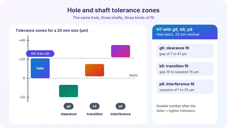
So Ø25 H7 is a hole from 25.000 to 25.021 mm, and Ø25 g6 is a shaft from 24.980 to 24.993 mm. In the hole-basis system (most common), all holes are H and the fit is chosen with the shaft letter.
Types of fit.
- Clearance: there is always a gap. H7/g6 for sliding fits: gap from
0 − (−7) = 7 µmto21 − (−20) = 41 µm. - Transition: might have a small gap or a small squeeze. H7/k6: from a gap of
21 − 2 = 19 µmto a squeeze of15 µm. - Interference: always a squeeze, for press fits. H7/p6: squeeze from 1 to 35 µm (the shaft ranges from +22 to +35 µm and the hole from 0 to +21).
Tolerance and cost. A tighter tolerance needs a more capable process, more careful setup and more inspection, so the cost climbs steeply. Typical ranges from experience: drilled holes about IT10 to IT12, milling IT8 to IT10, turning IT7 to IT9, reaming and boring IT6 to IT8, and grinding IT5 to IT6. Specify the loosest tolerance that works.
Tolerance stack-up
When parts stack in a line, their tolerances add. A stack of three blocks of 20.00 ± 0.05, 15.00 ± 0.03 and 10.00 ± 0.02 mm has a nominal length of 45.00 mm.
- Worst case: all parts at an extreme at the same time:
± (0.05 + 0.03 + 0.02) = ± 0.10 mm. This is certain, but pessimistic. - Root sum of squares (RSS): if the variations are independent and random, extremes rarely coincide:
± √(0.05² + 0.03² + 0.02²) = ± √0.0038 = ± 0.062 mm. This is statistical: it assumes processes are centered and approximately normal, so use it only with evidence.
A designer must choose between 100 percent assurance with tighter, costlier tolerances (worst case) and a small risk with looser, cheaper tolerances (statistical).
Geometric dimensioning and tolerancing (GD&T)
Size tolerances do not say how flat, round, straight or well-located a feature must be. A plate with a thickness within tolerance can still be warped. GD&T, defined in standards such as ASME Y14.5 and the ISO GPS series, adds symbols for these:
- Form: flatness, straightness, circularity, cylindricity.
- Orientation: perpendicularity, parallelism, angularity.
- Location: position, concentricity, symmetry.
- Runout: how much a feature wobbles when rotated about a datum axis.
- Profile: how closely a surface follows its ideal shape.
A feature control frame states the symbol, the tolerance value and the datums. Datums (the A, B and C of the drawing) reflect how the part sits in its assembly, so the inspector measures from the same references the designer had in mind. A material condition modifier such as MMC (maximum material condition, the size at which the feature has the most material: the smallest hole or largest shaft) adds a bonus tolerance: as a hole departs from its smallest size, its position tolerance may grow by the same amount, because a larger hole accommodates a bigger position error without hurting assembly.
Worked example. A hole is specified Ø10.0 to Ø10.2 with a position tolerance of Ø0.10 at MMC. At the smallest hole (Ø10.0, MMC) the position tolerance is 0.10 mm. A hole that measures Ø10.12 has departed 0.12 mm from MMC, so the position tolerance becomes 0.10 + 0.12 = 0.22 mm. Without the modifier, parts that would assemble perfectly could be rejected.
Surface finish
Roughness is described by Ra, the arithmetic average of the height deviations in µm. Typical values: ground 0.1 to 1.6, turned and milled 0.4 to 6.3, sand cast 12 to 25. Smoother finishes cost more; bearing surfaces and seals need them, but most surfaces do not.
Measuring instruments
- Calipers (vernier, dial, digital): resolution commonly 0.01 mm, accuracy around ±0.02 mm. Quick but easy to misuse by tilting or squeezing too hard.
- Micrometers: resolution 0.001 mm (or finer), and a ratchet gives a repeatable measuring force. The standard for turned parts to about ±0.005 mm.
- Dial and digital indicators, height gauges: compare a surface with a reference, and measure runout and flatness.
- Gauge blocks: calibrated steel or ceramic blocks of known thickness that serve as length references and for calibrating other instruments.
- Go/no-go gauges: a "go" plug that must enter the hole and a "no-go" plug that must not. Fast and needs no skill; it says "in or out", not by how much.
- Coordinate measuring machines (CMMs): a probe touches the part at many points and the machine computes sizes, positions and form errors in 3D, with uncertainties of a few micrometers. Programs follow the datum scheme of the drawing.
- Optical and laser systems, profilometers for roughness, and computed tomography for internal features of printed or cast parts.
Temperature matters
Industrial standards define the reference temperature for dimensional measurement as 20 °C. A part that is warmer is longer: ΔL = α L ΔT. Steel has α ≈ 11.5 × 10⁻⁶ K⁻¹, so a 100 mm steel part at 30 °C is 100 × 11.5×10⁻⁶ × 10 = 0.0115 mm longer, about 11.5 µm, which is larger than an IT6 tolerance. Aluminum (α ≈ 23 × 10⁻⁶) doubles the effect. That is why precision work is done in temperature-controlled rooms and why parts are allowed to "soak" before they are measured.
Uncertainty and the 10:1 rule
Every measurement has uncertainty: resolution, instrument error, operator technique, temperature and the part itself. A traditional guideline, the "rule of ten", says the instrument should be about ten times more precise than the tolerance (four to one is often accepted in practice). A gauge R&R study measures how much of the observed variation comes from the measuring system: the usual guidance classes a gauge using under about 10 percent of the tolerance as good, 10 to 30 percent as marginal, and above 30 percent as unacceptable.
Common misconceptions
"A tighter tolerance means better quality." It means higher cost. Quality is achieved when the part meets its functional requirement.
"The digital caliper shows 0.01 mm, so it is accurate to 0.01 mm." Resolution is not accuracy. Instrument error, force and alignment add up to more than the last digit.
"Parts within tolerance always assemble." Stack-ups, form errors and location errors can still cause trouble, which is why GD&T and assembly analysis exist.
Try it
Check a hole and shaft pair: enter their limits and see the type of fit and the extremes of the gap.
Next, compare a worst-case stack-up with a statistical one by simulation, and compute the thermal growth error.
Press Run (or Ctrl + Enter) to see the result here.
Program input · what you'd type while the program runs
Type the answers before you press Run, one per line. Each time the program reads a line (with input()), it gets the next line from this box.
Check your understanding
Quick check · 5 questions
of 5 answered You scored / 5 · perfect!
-
1. A shaft is 40.00 +0.00 / −0.03 mm. What is its tolerance?
The tolerance is the difference between the limits: 40.00 − 39.97 = 0.03 mm. -
2. Three parts of tolerance ±0.04, ±0.03 and ±0.12 mm are stacked. What is the worst-case stack tolerance?
Worst case adds the tolerances: 0.04 + 0.03 + 0.12 = 0.19 mm. RSS would give about ±0.13 mm. -
3. Which fit always leaves a squeeze between the shaft and the hole?
In an interference fit even the largest hole is smaller than the smallest shaft, so assembly requires pressing or heating. -
4. A hole of Ø10.00 to Ø10.15 has a position tolerance of Ø0.08 at MMC. The hole measures Ø10.10. What position tolerance is allowed?
The hole is 0.10 mm larger than MMC (10.00), which gives a bonus of 0.10 mm: 0.08 + 0.10 = 0.18 mm. -
5. A 200 mm aluminum part (α = 23×10⁻⁶ per K) is measured at 25 °C. How much longer than at 20 °C is it?
ΔL = α L ΔT = 23×10⁻⁶ × 200 mm × 5 K = 0.023 mm = 23 µm.
Summary
- A tolerance is the permitted variation; ISO 286 provides standard tolerance grades (IT) and position letters for holes and shafts.
- Fits are clearance, transition or interference; H7/g6, H7/k6 and H7/p6 give examples of each.
- Stack-ups add tolerances: worst case linearly, statistical by root sum of squares.
- GD&T controls form, orientation, location and runout from datums; MMC gives bonus tolerance.
- Measuring instruments differ in resolution and accuracy; 20 °C is the reference temperature, and uncertainty must be small against the tolerance.
Track your progress
Create a free account to tick off lessons and pick up where you left off on any device.
of Manufacturing Processes lessons completed